

9.2 Hydraulic Turbine Types
321
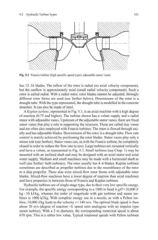
has 12–16 blades. The inflow of the rotor is radial (no axial velocity component),
but the outflow is approximately axial (small radial velocity component). Such a
rotor is called radial. With a radial rotor, rotor blades cannot be adjusted. Strongly
different rotor forms are used (see further below). Downstream of the rotor is a
draught tube. With the type represented, the draught tube is modelled in the concrete
structure. It can also be made of steel.
A Kaplan turbine, represented in Fig. 9.3, is an axial machine with a high degree
of reaction (0.75 and higher). The turbine shown has a volute supply and a radial
stator with adjustable vanes. Upstream of the adjustable stator vanes, there are fixed
stator vanes that play a role in supporting the structure. These are called stay vanes
and are often also employed with Francis turbines. The rotor is flowed through axially and has adjustable blades. Downstream of the rotor is a draught tube. Flow rate
control is mainly achieved by positioning the rotor blades. Stator vanes play only a
minor role (see further). Stator vanes can, as with the Francis turbine, be completely
closed in order to reduce the flow rate to zero. Large turbines are mounted vertically
and have a volute, as represented in Fig. 9.3. Small turbines (see Chap. 1) may be
mounted with an inclined shaft and may be designed with an axial stator and axial
water supply. Medium and small machines may be made with a horizontal shaft as
well (see further: bulb turbines). The rotor usually has 4–6 blades. Kaplan turbines
sometimes are described as propeller turbines due to the resemblance of the rotor
to a ship propeller. There also exist mixed-flow rotor forms with adjustable rotor
blades. Mixed-flow machines have a lower degree of reaction than axial machines
and have properties in between those of Francis and Kaplan turbines.
Hydraulic turbines are of single-stage type, due to their very low specific energy.
For example, the specific energy corresponding to a 1000 m head is gH ≈ 10,000 J/
kg = 10 kJ/kg, whereas the order of magnitude with gas turbines and steam turbines is 1000 kJ/kg. With complete energy use in a nozzle, as with a Pelton turbine, 10,000 J/kg leads to the velocity v ≈ 140 m/s. The optimal blade speed is then
about 70 m/s (degree of reaction = 0, speed ratio analogous with an impulse type
steam turbine). With a 2 m diameter, the corresponding rotational speed is about
670 rpm. This is a rather low value. Typical rotational speeds with Pelton turbines
Fig. 9.2 Francis turbine (high specific speed type); adjustable stator vanes
321
has 12–16 blades. The inflow of the rotor is radial (no axial velocity component),
but the outflow is approximately axial (small radial velocity component). Such a
rotor is called radial. With a radial rotor, rotor blades cannot be adjusted. Strongly
different rotor forms are used (see further below). Downstream of the rotor is a
draught tube. With the type represented, the draught tube is modelled in the concrete
structure. It can also be made of steel.
A Kaplan turbine, represented in Fig. 9.3, is an axial machine with a high degree
of reaction (0.75 and higher). The turbine shown has a volute supply and a radial
stator with adjustable vanes. Upstream of the adjustable stator vanes, there are fixed
stator vanes that play a role in supporting the structure. These are called stay vanes
and are often also employed with Francis turbines. The rotor is flowed through axially and has adjustable blades. Downstream of the rotor is a draught tube. Flow rate
control is mainly achieved by positioning the rotor blades. Stator vanes play only a
minor role (see further). Stator vanes can, as with the Francis turbine, be completely
closed in order to reduce the flow rate to zero. Large turbines are mounted vertically
and have a volute, as represented in Fig. 9.3. Small turbines (see Chap. 1) may be
mounted with an inclined shaft and may be designed with an axial stator and axial
water supply. Medium and small machines may be made with a horizontal shaft as
well (see further: bulb turbines). The rotor usually has 4–6 blades. Kaplan turbines
sometimes are described as propeller turbines due to the resemblance of the rotor
to a ship propeller. There also exist mixed-flow rotor forms with adjustable rotor
blades. Mixed-flow machines have a lower degree of reaction than axial machines
and have properties in between those of Francis and Kaplan turbines.
Hydraulic turbines are of single-stage type, due to their very low specific energy.
For example, the specific energy corresponding to a 1000 m head is gH ≈ 10,000 J/
kg = 10 kJ/kg, whereas the order of magnitude with gas turbines and steam turbines is 1000 kJ/kg. With complete energy use in a nozzle, as with a Pelton turbine, 10,000 J/kg leads to the velocity v ≈ 140 m/s. The optimal blade speed is then
about 70 m/s (degree of reaction = 0, speed ratio analogous with an impulse type
steam turbine). With a 2 m diameter, the corresponding rotational speed is about
670 rpm. This is a rather low value. Typical rotational speeds with Pelton turbines
Fig. 9.2 Francis turbine (high specific speed type); adjustable stator vanes