

7
1.4 Basic Laws for Stationary Duct Parts
We first derive some basic laws for an elementary duct part, stationary in an absolute frame. The geometry is less complex than within a turbomachine. Gradually, we
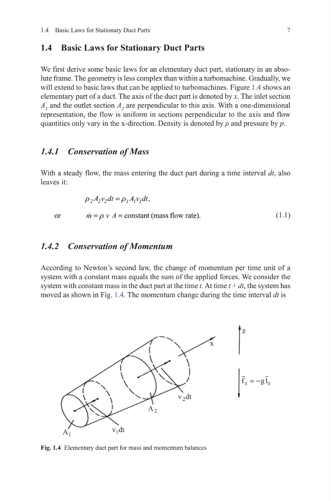
will extend to basic laws that can be applied to turbomachines. Figure 1.4 shows an
elementary part of a duct. The axis of the duct part is denoted by x. The inlet section
A 1 and the outlet section A 2 are perpendicular to this axis. With a one-dimensional
representation, the flow is uniform in sections perpendicular to the axis and flow
quantities only vary in the x-direction. Density is denoted by ρ and pressure by p.
1.4.1 Conservation of Mass
With a steady flow, the mass entering the duct part during a time interval dt, also
leaves it:
(1.1)
1.4.2 Conservation of Momentum
According to Newton’s second law, the change of momentum per time unit of a
system with a constant mass equals the sum of the applied forces. We consider the
system with constant mass in the duct part at the time t. At time t + dt, the system has
moved as shown in Fig. 1.4. The momentum change during the time interval dt is
,
2 2 2
1 1 1
A v dt
A v dt
r
r
=
or
constant (mass flow rate).
m
v A
r
=
=
Fig. 1.4 Elementary duct part for mass and momentum balances
1.4 Basic Laws for Stationary Duct Parts
1.4 Basic Laws for Stationary Duct Parts
We first derive some basic laws for an elementary duct part, stationary in an absolute frame. The geometry is less complex than within a turbomachine. Gradually, we
will extend to basic laws that can be applied to turbomachines. Figure 1.4 shows an
elementary part of a duct. The axis of the duct part is denoted by x. The inlet section
A 1 and the outlet section A 2 are perpendicular to this axis. With a one-dimensional
representation, the flow is uniform in sections perpendicular to the axis and flow
quantities only vary in the x-direction. Density is denoted by ρ and pressure by p.
1.4.1 Conservation of Mass
With a steady flow, the mass entering the duct part during a time interval dt, also
leaves it:
(1.1)
1.4.2 Conservation of Momentum
According to Newton’s second law, the change of momentum per time unit of a
system with a constant mass equals the sum of the applied forces. We consider the
system with constant mass in the duct part at the time t. At time t + dt, the system has
moved as shown in Fig. 1.4. The momentum change during the time interval dt is
,
2 2 2
1 1 1
A v dt
A v dt
r
r
=
or
constant (mass flow rate).
m
v A
r
=
=
Fig. 1.4 Elementary duct part for mass and momentum balances
1.4 Basic Laws for Stationary Duct Parts