

8.4 Component Shaping
301
no bearing is required at the suction side. This is possible with many single-stage
pumps (see Fig. 1.13 in Chap. 1). A bearing may be mounted on a bend at the suction side, but the bend impairs the flow uniformity at the rotor entrance and takes up
a lot of space. Therefore, an inlet bend is seldom used, sometimes with larger axial
pumps. With centrifugal pumps, a volute-shaped suction chamber is mostly applied,
requiring less axial length. Figure 8.13 sketches an orthogonal and a meridional section of the suction chambers of a double-suction pump. A double-suction rotor is a
form of internal parallel connection (see further Fig. 8.19). The volute shape of the
suction chambers is not complete. Part of the flow is led directly to the suction eye
of the rotors. The pre-swirl of the inlet flow may be corrected by vanes in a stator
inlet part to the rotor.
8.4.4 Pump Outlet
Fluid is conveyed from the rotor to the discharge pipe or to the next stage and kinetic energy is converted into pressure. The first function is mostly realised by a volute
followed by a linear diffuser (see further Fig. 8.15). The kinetic energy conversion
may also be done upstream of the volute with a vaned or a vaneless diffuser ring.
These elements are discussed below.
8.4.5 Vaneless Diffuser Rings
A vaneless diffuser ring consists of two circular surfaces forming the diffuser walls.
The axial width ( b) may be constant or vary with the radius r. Assuming that no
external forces affect the fluid, the flow has constant angular momentum:
(8.20)
.
=
u
v r cst
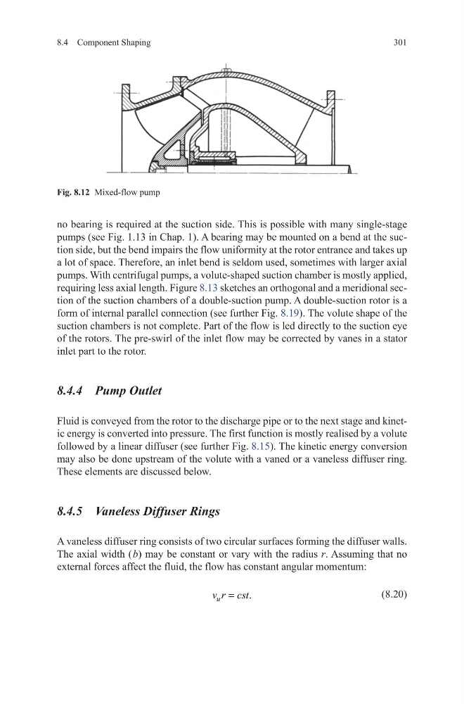
Fig. 8.12 Mixed-flow pump
301
no bearing is required at the suction side. This is possible with many single-stage
pumps (see Fig. 1.13 in Chap. 1). A bearing may be mounted on a bend at the suction side, but the bend impairs the flow uniformity at the rotor entrance and takes up
a lot of space. Therefore, an inlet bend is seldom used, sometimes with larger axial
pumps. With centrifugal pumps, a volute-shaped suction chamber is mostly applied,
requiring less axial length. Figure 8.13 sketches an orthogonal and a meridional section of the suction chambers of a double-suction pump. A double-suction rotor is a
form of internal parallel connection (see further Fig. 8.19). The volute shape of the
suction chambers is not complete. Part of the flow is led directly to the suction eye
of the rotors. The pre-swirl of the inlet flow may be corrected by vanes in a stator
inlet part to the rotor.
8.4.4 Pump Outlet
Fluid is conveyed from the rotor to the discharge pipe or to the next stage and kinetic energy is converted into pressure. The first function is mostly realised by a volute
followed by a linear diffuser (see further Fig. 8.15). The kinetic energy conversion
may also be done upstream of the volute with a vaned or a vaneless diffuser ring.
These elements are discussed below.
8.4.5 Vaneless Diffuser Rings
A vaneless diffuser ring consists of two circular surfaces forming the diffuser walls.
The axial width ( b) may be constant or vary with the radius r. Assuming that no
external forces affect the fluid, the flow has constant angular momentum:
(8.20)
.
=
u
v r cst
Fig. 8.12 Mixed-flow pump