

8 Pumps
302
(8.21)
For b = constant, it follows that
(8.22)
Within a diffuser with a constant width, streamlines are logarithmic spirals. The velocity magnitude decreases inversely with the radius. When the difference between
the inlet velocity and the outlet velocity is great, i.e. when much kinetic energy has
to be converted into pressure energy, the external diameter of the vaneless diffuser
becomes large. Due to the long streamlines, friction losses become high. These
friction losses may still increase at a flow rate below the design value: the angle a
then increases and streamlines lengthen. When the width increases with the radius,
streamlines are even longer than with parallel walls. So, vaneless diffusers are only
suitable to convert low amounts of kinetic energy.
8.4.6 Vaned Diffuser Rings
In case of parallel diffuser sidewalls:
.
r
v r cst
=
A faster diffusion compared to the
vaneless diffuser is achieved if v u decreases faster. This requires exertion of tangential forces onto the fluid by means of diffuser vanes. The vanes are mounted more
radially than the streamlines with vaneless diffusers. With vaned radial diffusers,
two nearby vanes only overlap over a limited length (Fig. 8.14). Diffusion mainly
occurs within the widening section BC of the channels formed by two adjacent
vanes. The wall AB, constituting the supply to the overlap section, principally is
a logarithmic spiral. Similarly, the wall CD is also of logarithmic spiral form. The
final vane shape and the optimum number of vanes follow from optimisation, which
nowadays typically is a CFD-optimisation. Mostly, the number of diffuser blades is
The mass flow imposes
.
p
=
r
2 rbv cst
.
a =
=
u
r
v
tg
cst
v
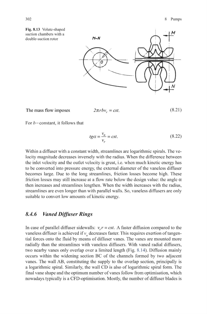
Fig. 8.13 Volute-shaped
suction chambers with a
double-suction rotor
302
(8.21)
For b = constant, it follows that
(8.22)
Within a diffuser with a constant width, streamlines are logarithmic spirals. The velocity magnitude decreases inversely with the radius. When the difference between
the inlet velocity and the outlet velocity is great, i.e. when much kinetic energy has
to be converted into pressure energy, the external diameter of the vaneless diffuser
becomes large. Due to the long streamlines, friction losses become high. These
friction losses may still increase at a flow rate below the design value: the angle a
then increases and streamlines lengthen. When the width increases with the radius,
streamlines are even longer than with parallel walls. So, vaneless diffusers are only
suitable to convert low amounts of kinetic energy.
8.4.6 Vaned Diffuser Rings
In case of parallel diffuser sidewalls:
.
r
v r cst
=
A faster diffusion compared to the
vaneless diffuser is achieved if v u decreases faster. This requires exertion of tangential forces onto the fluid by means of diffuser vanes. The vanes are mounted more
radially than the streamlines with vaneless diffusers. With vaned radial diffusers,
two nearby vanes only overlap over a limited length (Fig. 8.14). Diffusion mainly
occurs within the widening section BC of the channels formed by two adjacent
vanes. The wall AB, constituting the supply to the overlap section, principally is
a logarithmic spiral. Similarly, the wall CD is also of logarithmic spiral form. The
final vane shape and the optimum number of vanes follow from optimisation, which
nowadays typically is a CFD-optimisation. Mostly, the number of diffuser blades is
The mass flow imposes
.
p
=
r
2 rbv cst
.
a =
=
u
r
v
tg
cst
v
Fig. 8.13 Volute-shaped
suction chambers with a
double-suction rotor