

8 Pumps
296
8.2.3 Self-Priming Centrifugal Pump
The splattering principle with generation of an emulsion may be applied to
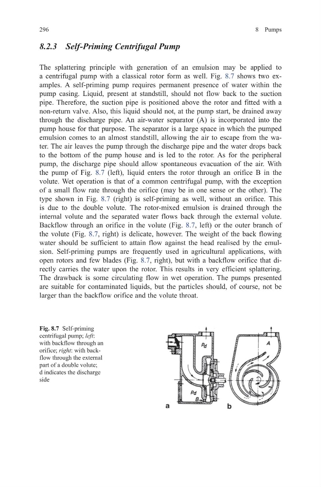
a centrifugal pump with a classical rotor form as well. Fig. 8.7 shows two examples. A self-priming pump requires permanent presence of water within the
pump casing. Liquid, present at standstill, should not flow back to the suction
pipe. Therefore, the suction pipe is positioned above the rotor and fitted with a
non-return valve. Also, this liquid should not, at the pump start, be drained away
through the discharge pipe. An air-water separator (A) is incorporated into the
pump house for that purpose. The separator is a large space in which the pumped
emulsion comes to an almost standstill, allowing the air to escape from the water. The air leaves the pump through the discharge pipe and the water drops back
to the bottom of the pump house and is led to the rotor. As for the peripheral
pump, the discharge pipe should allow spontaneous evacuation of the air. With
the pump of Fig. 8.7 (left), liquid enters the rotor through an orifice B in the
volute. Wet operation is that of a common centrifugal pump, with the exception
of a small flow rate through the orifice (may be in one sense or the other). The
type shown in Fig. 8.7 (right) is self-priming as well, without an orifice. This
is due to the double volute. The rotor-mixed emulsion is drained through the
internal volute and the separated water flows back through the external volute.
Backflow through an orifice in the volute (Fig. 8.7, left) or the outer branch of
the volute (Fig. 8.7, right) is delicate, however. The weight of the back flowing
water should be sufficient to attain flow against the head realised by the emulsion. Self-priming pumps are frequently used in agricultural applications, with
open rotors and few blades (Fig. 8.7, right), but with a backflow orifice that directly carries the water upon the rotor. This results in very efficient splattering.
The drawback is some circulating flow in wet operation. The pumps presented
are suitable for contaminated liquids, but the particles should, of course, not be
larger than the backflow orifice and the volute throat.
Fig. 8.7 Self-priming
centrifugal pump; left:
with backflow through an
orifice; right: with backflow through the external
part of a double volute;
d indicates the discharge
side
296
8.2.3 Self-Priming Centrifugal Pump
The splattering principle with generation of an emulsion may be applied to
a centrifugal pump with a classical rotor form as well. Fig. 8.7 shows two examples. A self-priming pump requires permanent presence of water within the
pump casing. Liquid, present at standstill, should not flow back to the suction
pipe. Therefore, the suction pipe is positioned above the rotor and fitted with a
non-return valve. Also, this liquid should not, at the pump start, be drained away
through the discharge pipe. An air-water separator (A) is incorporated into the
pump house for that purpose. The separator is a large space in which the pumped
emulsion comes to an almost standstill, allowing the air to escape from the water. The air leaves the pump through the discharge pipe and the water drops back
to the bottom of the pump house and is led to the rotor. As for the peripheral
pump, the discharge pipe should allow spontaneous evacuation of the air. With
the pump of Fig. 8.7 (left), liquid enters the rotor through an orifice B in the
volute. Wet operation is that of a common centrifugal pump, with the exception
of a small flow rate through the orifice (may be in one sense or the other). The
type shown in Fig. 8.7 (right) is self-priming as well, without an orifice. This
is due to the double volute. The rotor-mixed emulsion is drained through the
internal volute and the separated water flows back through the external volute.
Backflow through an orifice in the volute (Fig. 8.7, left) or the outer branch of
the volute (Fig. 8.7, right) is delicate, however. The weight of the back flowing
water should be sufficient to attain flow against the head realised by the emulsion. Self-priming pumps are frequently used in agricultural applications, with
open rotors and few blades (Fig. 8.7, right), but with a backflow orifice that directly carries the water upon the rotor. This results in very efficient splattering.
The drawback is some circulating flow in wet operation. The pumps presented
are suitable for contaminated liquids, but the particles should, of course, not be
larger than the backflow orifice and the volute throat.
Fig. 8.7 Self-priming
centrifugal pump; left:
with backflow through an
orifice; right: with backflow through the external
part of a double volute;
d indicates the discharge
side