

8.2 Priming of Pumps: Self-Priming Types
295
When the flow rate through the pump is lower, the pitch of the helical motion within
the side channels becomes lower. Work (8.17) is done each time water is passing
through the rotor. So, the head increases strongly when the flow rate diminishes.
Efficiency is low, due to the short turns of the flow, leakage losses and friction
losses within the water ring. The head of a side channel pump is 4–10 times higher
than that of a common centrifugal pump with the same peripheral speed, as the
water flows repeatedly through the rotor. Side channel pumps are designed for the
0.03 < Ω s < 0.6 range. Their efficiency may maximally attain 50 %. A rather low efficiency is no drawback with small power applications, as a small centrifugal pump
does not attain a high efficiency either.
8.2.2 Peripheral Pump (regenerative pump)
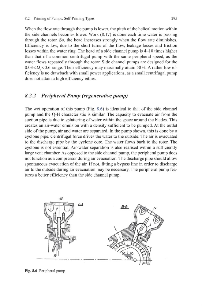
The wet operation of this pump (Fig. 8.6) is identical to that of the side channel
pump and the Q-H characteristic is similar. The capacity to evacuate air from the
suction pipe is due to splattering of water within the space around the blades. This
creates an air-water emulsion with a density sufficient to be pumped. At the outlet
side of the pump, air and water are separated. In the pump shown, this is done by a
cyclone pipe. Centrifugal force drives the water to the outside. The air is evacuated
to the discharge pipe by the cyclone core. The water flows back to the rotor. The
cyclone is not essential. Air-water separation is also realised within a sufficiently
large vent chamber. As opposed to the side channel pump, the peripheral pump does
not function as a compressor during air evacuation. The discharge pipe should allow
spontaneous evacuation of the air. If not, fitting a bypass line in order to discharge
air to the outside during air evacuation may be necessary. The peripheral pump features a better efficiency than the side channel pump.
Fig. 8.6 Peripheral pump
295
When the flow rate through the pump is lower, the pitch of the helical motion within
the side channels becomes lower. Work (8.17) is done each time water is passing
through the rotor. So, the head increases strongly when the flow rate diminishes.
Efficiency is low, due to the short turns of the flow, leakage losses and friction
losses within the water ring. The head of a side channel pump is 4–10 times higher
than that of a common centrifugal pump with the same peripheral speed, as the
water flows repeatedly through the rotor. Side channel pumps are designed for the
0.03 < Ω s < 0.6 range. Their efficiency may maximally attain 50 %. A rather low efficiency is no drawback with small power applications, as a small centrifugal pump
does not attain a high efficiency either.
8.2.2 Peripheral Pump (regenerative pump)
The wet operation of this pump (Fig. 8.6) is identical to that of the side channel
pump and the Q-H characteristic is similar. The capacity to evacuate air from the
suction pipe is due to splattering of water within the space around the blades. This
creates an air-water emulsion with a density sufficient to be pumped. At the outlet
side of the pump, air and water are separated. In the pump shown, this is done by a
cyclone pipe. Centrifugal force drives the water to the outside. The air is evacuated
to the discharge pipe by the cyclone core. The water flows back to the rotor. The
cyclone is not essential. Air-water separation is also realised within a sufficiently
large vent chamber. As opposed to the side channel pump, the peripheral pump does
not function as a compressor during air evacuation. The discharge pipe should allow
spontaneous evacuation of the air. If not, fitting a bypass line in order to discharge
air to the outside during air evacuation may be necessary. The peripheral pump features a better efficiency than the side channel pump.
Fig. 8.6 Peripheral pump