

8 Pumps
286
drop, may be lower. Thus the value of
p min
( C )
−
at zero incidence may fall until
about 0.5. With axial pumps, blades always feature a hydrodynamic profile and the
p min
( C )
−
value may be similarly low. Additional acceleration occurs with positive
incidence, increasing
p min
( C )
−
by 0.2–0.3 per degree of incidence until a limit
value is attained when the flow separates, which occurs at 5–6° incidence. In case
of negative incidence, suction may occur at the leading edge of the pressure side and
p min
( C )
−
may increase rather strongly. The
p min
( C )
−
change is thus very strong
with the variation of incidence. Figure 8.1 also sketches the pressure distribution in
the presence of a large cavitation bubble. There is vapour pressure within the bubble, levelling out the minimum in the pressure profile. A bubble that is sufficiently
big for causing erosion typically features a
p min
( C )
−
plateau value around 0.3.
This value increases somewhat at positive incidence (flow rate lower than design).
When the cavitation zone expands so much that it obstructs the through-flow, pump
performance is affected. Head and efficiency decrease. With a flow rate smaller
than the design value, obstruction becomes noticeable when the separation zone
extends into the throat of the blade passage. The corresponding value of
p min
( C )
−
is typically about 0.15 [6]. With a flow rate larger than the design value, obstruction
already becomes noticeable with a smaller cavitation zone, but the corresponding
p min
( C )
−
is of the same order of magnitude. The cavitation zone in Fig. 8.1 is
highly unsteady in reality. Fluid parts are continuously entering and evaporating and
fluid parts also continuously leave the zone and implode.
8.1.3 Cavitation Assessment: Cavitation Number and Required
Net Positive Suction Height
Two concepts are applied for assessing cavitation risk and cavitation degree.
The cavitation number is a pressure coefficient using the pressure and the velocity of the oncoming flow, like a pressure coefficient for description of the pressure
distribution on a blade:
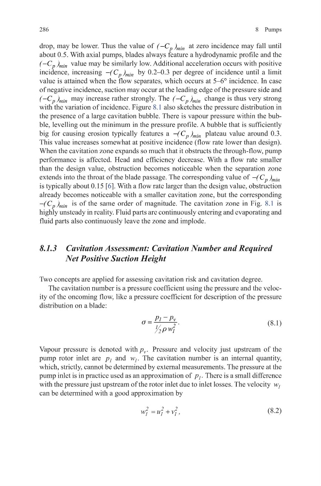
(8.1)
Vapour pressure is denoted with p v . Pressure and velocity just upstream of the
pump rotor inlet are p 1 and w 1 . The cavitation number is an internal quantity,
which, strictly, cannot be determined by external measurements. The pressure at the
pump inlet is in practice used as an approximation of p 1 . There is a small difference
with the pressure just upstream of the rotor inlet due to inlet losses. The velocity w 1
can be determined with a good approximation by
(8.2)
s
r
−
=
1
v
2
1
1
2
p p .
w
w
u v
1
2
1
2
1
2
= + ,
286
drop, may be lower. Thus the value of
p min
( C )
−
at zero incidence may fall until
about 0.5. With axial pumps, blades always feature a hydrodynamic profile and the
p min
( C )
−
value may be similarly low. Additional acceleration occurs with positive
incidence, increasing
p min
( C )
−
by 0.2–0.3 per degree of incidence until a limit
value is attained when the flow separates, which occurs at 5–6° incidence. In case
of negative incidence, suction may occur at the leading edge of the pressure side and
p min
( C )
−
may increase rather strongly. The
p min
( C )
−
change is thus very strong
with the variation of incidence. Figure 8.1 also sketches the pressure distribution in
the presence of a large cavitation bubble. There is vapour pressure within the bubble, levelling out the minimum in the pressure profile. A bubble that is sufficiently
big for causing erosion typically features a
p min
( C )
−
plateau value around 0.3.
This value increases somewhat at positive incidence (flow rate lower than design).
When the cavitation zone expands so much that it obstructs the through-flow, pump
performance is affected. Head and efficiency decrease. With a flow rate smaller
than the design value, obstruction becomes noticeable when the separation zone
extends into the throat of the blade passage. The corresponding value of
p min
( C )
−
is typically about 0.15 [6]. With a flow rate larger than the design value, obstruction
already becomes noticeable with a smaller cavitation zone, but the corresponding
p min
( C )
−
is of the same order of magnitude. The cavitation zone in Fig. 8.1 is
highly unsteady in reality. Fluid parts are continuously entering and evaporating and
fluid parts also continuously leave the zone and implode.
8.1.3 Cavitation Assessment: Cavitation Number and Required
Net Positive Suction Height
Two concepts are applied for assessing cavitation risk and cavitation degree.
The cavitation number is a pressure coefficient using the pressure and the velocity of the oncoming flow, like a pressure coefficient for description of the pressure
distribution on a blade:
(8.1)
Vapour pressure is denoted with p v . Pressure and velocity just upstream of the
pump rotor inlet are p 1 and w 1 . The cavitation number is an internal quantity,
which, strictly, cannot be determined by external measurements. The pressure at the
pump inlet is in practice used as an approximation of p 1 . There is a small difference
with the pressure just upstream of the rotor inlet due to inlet losses. The velocity w 1
can be determined with a good approximation by
(8.2)
s
r
−
=
1
v
2
1
1
2
p p .
w
w
u v
1
2
1
2
1
2
= + ,