

8.1 Cavitation
287
where u 1 stands for the blade speed at rotor inlet and v 1 follows from the flow rate
and the through-flow area. The pressure p 1 for which there is incipient cavitation
on the blade determines a critical value of the cavitation number:
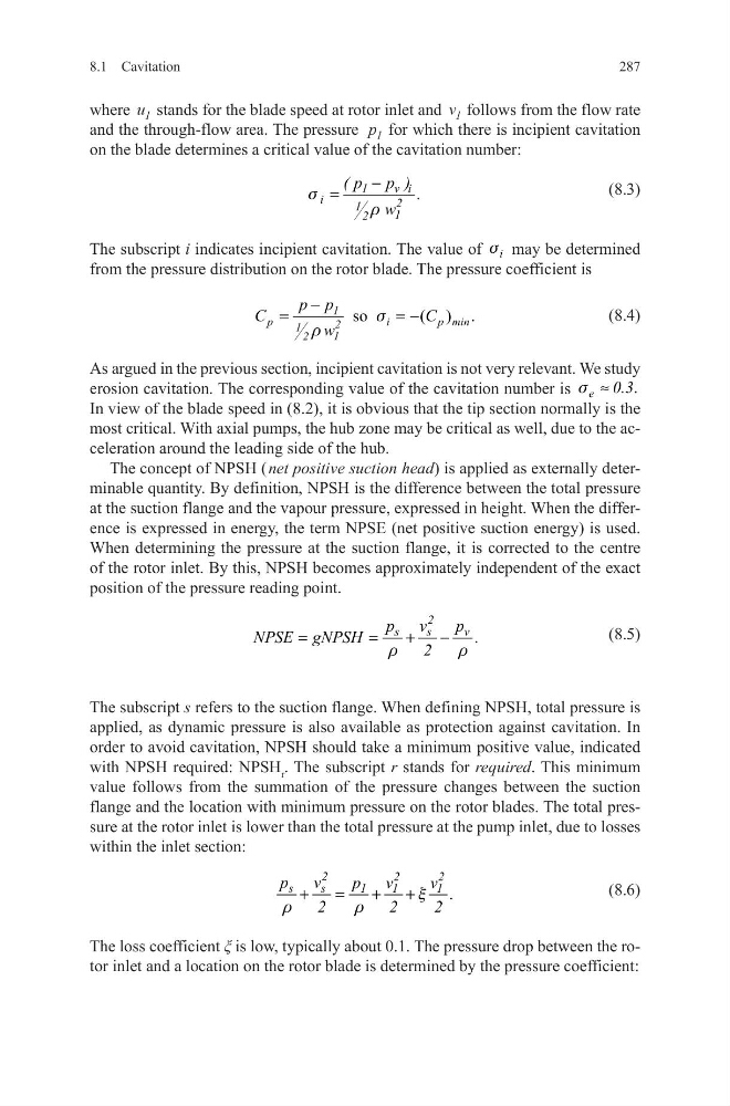
(8.3)
The subscript i indicates incipient cavitation. The value of s i may be determined
from the pressure distribution on the rotor blade. The pressure coefficient is
(8.4)
As argued in the previous section, incipient cavitation is not very relevant. We study
erosion cavitation. The corresponding value of the cavitation number is
.
s ≈
e
0.3
In view of the blade speed in (8.2), it is obvious that the tip section normally is the
most critical. With axial pumps, the hub zone may be critical as well, due to the acceleration around the leading side of the hub.
The concept of NPSH ( net positive suction head) is applied as externally determinable quantity. By definition, NPSH is the difference between the total pressure
at the suction flange and the vapour pressure, expressed in height. When the difference is expressed in energy, the term NPSE (net positive suction energy) is used.
When determining the pressure at the suction flange, it is corrected to the centre
of the rotor inlet. By this, NPSH becomes approximately independent of the exact
position of the pressure reading point.
(8.5)
The subscript s refers to the suction flange. When defining NPSH, total pressure is
applied, as dynamic pressure is also available as protection against cavitation. In
order to avoid cavitation, NPSH should take a minimum positive value, indicated
with NPSH required: NPSH r . The subscript r stands for required. This minimum
value follows from the summation of the pressure changes between the suction
flange and the location with minimum pressure on the rotor blades. The total pressure at the rotor inlet is lower than the total pressure at the pump inlet, due to losses
within the inlet section:
(8.6)
The loss coefficient ξ is low, typically about 0.1. The pressure drop between the rotor inlet and a location on the rotor blade is determined by the pressure coefficient:
1
v i
i
2
1
1
2
( p p ) .
w
s
r
−
=
so
(
.
)
1
p
i
p min
2
1
1
2
p p
C
C
w
s
r
−
=
= −
2
s
s
v
p
v
p
NPSE gNPSH
.
2
r
r
=
=
+
−
x
r
r
+
=
+
+
2
2
2
s
s
1
1
1
p
v
p v
v .
2
2
2
287
where u 1 stands for the blade speed at rotor inlet and v 1 follows from the flow rate
and the through-flow area. The pressure p 1 for which there is incipient cavitation
on the blade determines a critical value of the cavitation number:
(8.3)
The subscript i indicates incipient cavitation. The value of s i may be determined
from the pressure distribution on the rotor blade. The pressure coefficient is
(8.4)
As argued in the previous section, incipient cavitation is not very relevant. We study
erosion cavitation. The corresponding value of the cavitation number is
.
s ≈
e
0.3
In view of the blade speed in (8.2), it is obvious that the tip section normally is the
most critical. With axial pumps, the hub zone may be critical as well, due to the acceleration around the leading side of the hub.
The concept of NPSH ( net positive suction head) is applied as externally determinable quantity. By definition, NPSH is the difference between the total pressure
at the suction flange and the vapour pressure, expressed in height. When the difference is expressed in energy, the term NPSE (net positive suction energy) is used.
When determining the pressure at the suction flange, it is corrected to the centre
of the rotor inlet. By this, NPSH becomes approximately independent of the exact
position of the pressure reading point.
(8.5)
The subscript s refers to the suction flange. When defining NPSH, total pressure is
applied, as dynamic pressure is also available as protection against cavitation. In
order to avoid cavitation, NPSH should take a minimum positive value, indicated
with NPSH required: NPSH r . The subscript r stands for required. This minimum
value follows from the summation of the pressure changes between the suction
flange and the location with minimum pressure on the rotor blades. The total pressure at the rotor inlet is lower than the total pressure at the pump inlet, due to losses
within the inlet section:
(8.6)
The loss coefficient ξ is low, typically about 0.1. The pressure drop between the rotor inlet and a location on the rotor blade is determined by the pressure coefficient:
1
v i
i
2
1
1
2
( p p ) .
w
s
r
−
=
so
(
.
)
1
p
i
p min
2
1
1
2
p p
C
C
w
s
r
−
=
= −
2
s
s
v
p
v
p
NPSE gNPSH
.
2
r
r
=
=
+
−
x
r
r
+
=
+
+
2
2
2
s
s
1
1
1
p
v
p v
v .
2
2
2