

226
6 Steam Turbines
With reaction blading, there is an axial force on the rotor in the through-flow
sense. In the double-flow parts of Fig. 6.19, the axial forces in the opposite flow
senses balance each other. With the single flow HP part, the axial force is balanced
by an equilibrium piston. This is the cylindrical part at the right-hand side of the
rotor of Fig. 6.20, sealed at its periphery with labyrinth combs. The steam pressure
after the first stator row is at one side and the pressure at the outlet of the HP part at
the other side (the equilibrium piston is also visible in Fig. 6.29).
With HP and IP turbines, blades are mounted into tangential slots. With LP parts,
tangential slots are applied for the first stages and axial slots for the last ones (see
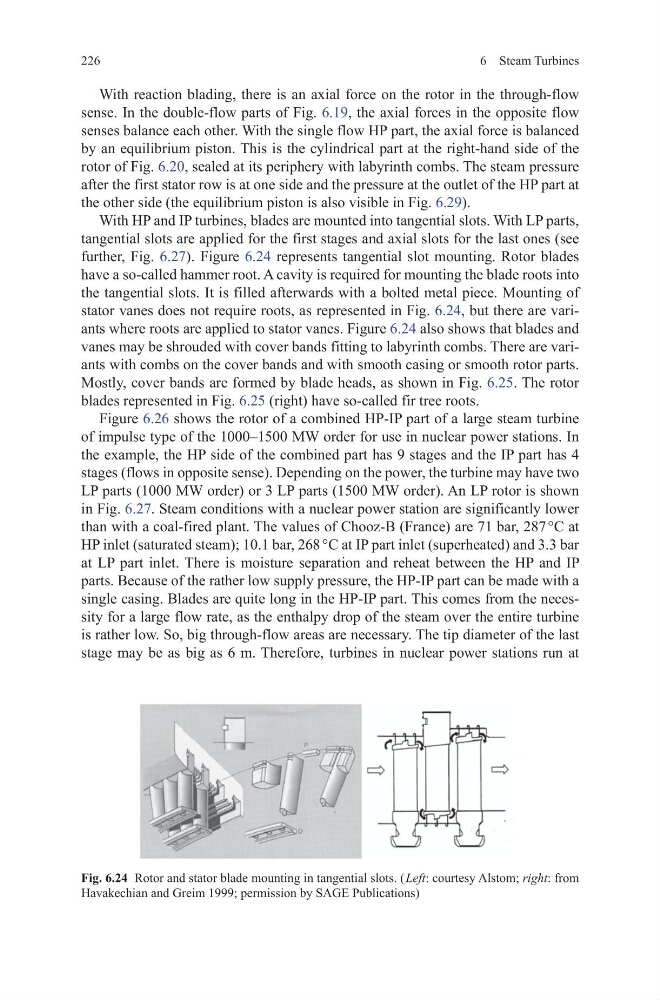
further, Fig. 6.27). Figure 6.24 represents tangential slot mounting. Rotor blades
have a so-called hammer root. A cavity is required for mounting the blade roots into
the tangential slots. It is filled afterwards with a bolted metal piece. Mounting of
stator vanes does not require roots, as represented in Fig. 6.24, but there are variants where roots are applied to stator vanes. Figure 6.24 also shows that blades and
vanes may be shrouded with cover bands fitting to labyrinth combs. There are variants with combs on the cover bands and with smooth casing or smooth rotor parts.
Mostly, cover bands are formed by blade heads, as shown in Fig. 6.25. The rotor
blades represented in Fig. 6.25 (right) have so-called fir tree roots.
Figure 6.26 shows the rotor of a combined HP-IP part of a large steam turbine
of impulse type of the 1000–1500 MW order for use in nuclear power stations. In
the example, the HP side of the combined part has 9 stages and the IP part has 4
stages (flows in opposite sense). Depending on the power, the turbine may have two
LP parts (1000 MW order) or 3 LP parts (1500 MW order). An LP rotor is shown
in Fig. 6.27. Steam conditions with a nuclear power station are significantly lower
than with a coal-fired plant. The values of Chooz-B (France) are 71 bar, 287 °C at
HP inlet (saturated steam); 10.1 bar, 268 °C at IP part inlet (superheated) and 3.3 bar
at LP part inlet. There is moisture separation and reheat between the HP and IP
parts. Because of the rather low supply pressure, the HP-IP part can be made with a
single casing. Blades are quite long in the HP-IP part. This comes from the necessity for a large flow rate, as the enthalpy drop of the steam over the entire turbine
is rather low. So, big through-flow areas are necessary. The tip diameter of the last
stage may be as big as 6 m. Therefore, turbines in nuclear power stations run at
Fig. 6.24 Rotor and stator blade mounting in tangential slots. ( Left: courtesy Alstom; right: from
Havakechian and Greim 1999; permission by SAGE Publications)
6 Steam Turbines
With reaction blading, there is an axial force on the rotor in the through-flow
sense. In the double-flow parts of Fig. 6.19, the axial forces in the opposite flow
senses balance each other. With the single flow HP part, the axial force is balanced
by an equilibrium piston. This is the cylindrical part at the right-hand side of the
rotor of Fig. 6.20, sealed at its periphery with labyrinth combs. The steam pressure
after the first stator row is at one side and the pressure at the outlet of the HP part at
the other side (the equilibrium piston is also visible in Fig. 6.29).
With HP and IP turbines, blades are mounted into tangential slots. With LP parts,
tangential slots are applied for the first stages and axial slots for the last ones (see
further, Fig. 6.27). Figure 6.24 represents tangential slot mounting. Rotor blades
have a so-called hammer root. A cavity is required for mounting the blade roots into
the tangential slots. It is filled afterwards with a bolted metal piece. Mounting of
stator vanes does not require roots, as represented in Fig. 6.24, but there are variants where roots are applied to stator vanes. Figure 6.24 also shows that blades and
vanes may be shrouded with cover bands fitting to labyrinth combs. There are variants with combs on the cover bands and with smooth casing or smooth rotor parts.
Mostly, cover bands are formed by blade heads, as shown in Fig. 6.25. The rotor
blades represented in Fig. 6.25 (right) have so-called fir tree roots.
Figure 6.26 shows the rotor of a combined HP-IP part of a large steam turbine
of impulse type of the 1000–1500 MW order for use in nuclear power stations. In
the example, the HP side of the combined part has 9 stages and the IP part has 4
stages (flows in opposite sense). Depending on the power, the turbine may have two
LP parts (1000 MW order) or 3 LP parts (1500 MW order). An LP rotor is shown
in Fig. 6.27. Steam conditions with a nuclear power station are significantly lower
than with a coal-fired plant. The values of Chooz-B (France) are 71 bar, 287 °C at
HP inlet (saturated steam); 10.1 bar, 268 °C at IP part inlet (superheated) and 3.3 bar
at LP part inlet. There is moisture separation and reheat between the HP and IP
parts. Because of the rather low supply pressure, the HP-IP part can be made with a
single casing. Blades are quite long in the HP-IP part. This comes from the necessity for a large flow rate, as the enthalpy drop of the steam over the entire turbine
is rather low. So, big through-flow areas are necessary. The tip diameter of the last
stage may be as big as 6 m. Therefore, turbines in nuclear power stations run at
Fig. 6.24 Rotor and stator blade mounting in tangential slots. ( Left: courtesy Alstom; right: from
Havakechian and Greim 1999; permission by SAGE Publications)