

225
6.8 Steam Turbine Construction Forms
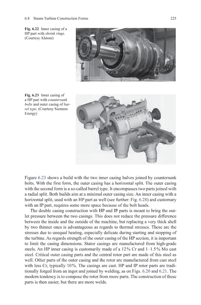
Figure 6.23 shows a build with the two inner casing halves joined by countersunk
bolts. With the first form, the outer casing has a horizontal split. The outer casing
with the second form is a so-called barrel type. It encompasses two parts joined with
a radial split. Both builds aim at a minimal outer casing size. An inner casing with a
horizontal split, used with an HP part as well (see further: Fig. 6.28) and customary
with an IP part, requires some more space because of the bolt heads.
The double casing construction with HP and IP parts is meant to bring the outlet pressure between the two casings. This does not reduce the pressure difference
between the inside and the outside of the machine, but replacing a very thick shell
by two thinner ones is advantageous as regards to thermal stresses. These are the
stresses due to unequal heating, especially delicate during starting and stopping of
the turbine. As regards strength of the outer casing of the HP section, it is important
to limit the casing dimensions. Stator casings are manufactured from high-grade
steels. An HP inner casing is customarily made of a 12 % Cr and 1–1.5 % Mo cast
steel. Critical outer casing parts and the central rotor part are made of this steel as
well. Other parts of the outer casing and the rotor are manufactured from cast steel
with less Cr, typically 10 %. The casings are cast. HP and IP rotor parts are traditionally forged from an ingot and joined by welding, as on Figs. 6.20 and 6.21. The
modern tendency is to compose the rotor from more parts. The construction of these
parts is then easier, but there are more welds.
Fig. 6.23 Inner casing of
a HP part with countersunk
bolts and outer casing of barrel type. (Courtesy Siemens
Energy)
Fig. 6.22 Inner casing of a
HP part with shrink rings.
(Courtesy Alstom)
6.8 Steam Turbine Construction Forms
Figure 6.23 shows a build with the two inner casing halves joined by countersunk
bolts. With the first form, the outer casing has a horizontal split. The outer casing
with the second form is a so-called barrel type. It encompasses two parts joined with
a radial split. Both builds aim at a minimal outer casing size. An inner casing with a
horizontal split, used with an HP part as well (see further: Fig. 6.28) and customary
with an IP part, requires some more space because of the bolt heads.
The double casing construction with HP and IP parts is meant to bring the outlet pressure between the two casings. This does not reduce the pressure difference
between the inside and the outside of the machine, but replacing a very thick shell
by two thinner ones is advantageous as regards to thermal stresses. These are the
stresses due to unequal heating, especially delicate during starting and stopping of
the turbine. As regards strength of the outer casing of the HP section, it is important
to limit the casing dimensions. Stator casings are manufactured from high-grade
steels. An HP inner casing is customarily made of a 12 % Cr and 1–1.5 % Mo cast
steel. Critical outer casing parts and the central rotor part are made of this steel as
well. Other parts of the outer casing and the rotor are manufactured from cast steel
with less Cr, typically 10 %. The casings are cast. HP and IP rotor parts are traditionally forged from an ingot and joined by welding, as on Figs. 6.20 and 6.21. The
modern tendency is to compose the rotor from more parts. The construction of these
parts is then easier, but there are more welds.
Fig. 6.23 Inner casing of
a HP part with countersunk
bolts and outer casing of barrel type. (Courtesy Siemens
Energy)
Fig. 6.22 Inner casing of a
HP part with shrink rings.
(Courtesy Alstom)