

224
6 Steam Turbines
6.8 Steam Turbine Construction Forms
6.8.1 Large Steam Turbines for Power Stations
Figure 6.19 sketches the lay-out of a steam turbine in the 1000 MW order for typical steam conditions 250 bar/565 °C/565 °C for use in coal-fired power stations. The
machine has 5 parts: a high-pressure part (HP), an intermediate-pressure part (IP)
and 3 low-pressure parts (LP). The high-pressure part has a single flow. There is a
reheat after the HP part. The intermediate part and each low-pressure part have two
flows. Multiplication of the number of flows as the expansion advances is necessary, because of the strong decrease of steam density.
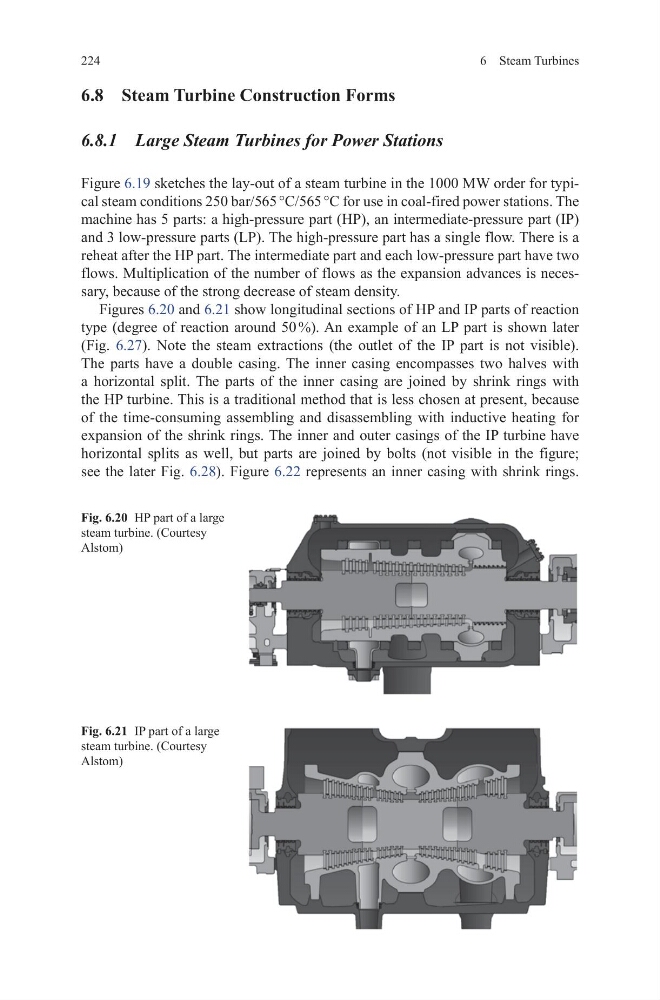
Figures 6.20 and 6.21 show longitudinal sections of HP and IP parts of reaction
type (degree of reaction around 50 %). An example of an LP part is shown later
(Fig. 6.27). Note the steam extractions (the outlet of the IP part is not visible).
The parts have a double casing. The inner casing encompasses two halves with
a horizontal split. The parts of the inner casing are joined by shrink rings with
the HP turbine. This is a traditional method that is less chosen at present, because
of the time-consuming assembling and disassembling with inductive heating for
expansion of the shrink rings. The inner and outer casings of the IP turbine have
horizontal splits as well, but parts are joined by bolts (not visible in the figure;
see the later Fig. 6.28). Figure 6.22 represents an inner casing with shrink rings.
Fig. 6.20 HP part of a large
steam turbine. (Courtesy
Alstom)
Fig. 6.21 IP part of a large
steam turbine. (Courtesy
Alstom)
6 Steam Turbines
6.8 Steam Turbine Construction Forms
6.8.1 Large Steam Turbines for Power Stations
Figure 6.19 sketches the lay-out of a steam turbine in the 1000 MW order for typical steam conditions 250 bar/565 °C/565 °C for use in coal-fired power stations. The
machine has 5 parts: a high-pressure part (HP), an intermediate-pressure part (IP)
and 3 low-pressure parts (LP). The high-pressure part has a single flow. There is a
reheat after the HP part. The intermediate part and each low-pressure part have two
flows. Multiplication of the number of flows as the expansion advances is necessary, because of the strong decrease of steam density.
Figures 6.20 and 6.21 show longitudinal sections of HP and IP parts of reaction
type (degree of reaction around 50 %). An example of an LP part is shown later
(Fig. 6.27). Note the steam extractions (the outlet of the IP part is not visible).
The parts have a double casing. The inner casing encompasses two halves with
a horizontal split. The parts of the inner casing are joined by shrink rings with
the HP turbine. This is a traditional method that is less chosen at present, because
of the time-consuming assembling and disassembling with inductive heating for
expansion of the shrink rings. The inner and outer casings of the IP turbine have
horizontal splits as well, but parts are joined by bolts (not visible in the figure;
see the later Fig. 6.28). Figure 6.22 represents an inner casing with shrink rings.
Fig. 6.20 HP part of a large
steam turbine. (Courtesy
Alstom)
Fig. 6.21 IP part of a large
steam turbine. (Courtesy
Alstom)