

223
6.8 Steam Turbine Construction Forms
Rotor work is then ∆W u v
v
uv
u
u
u
=
−
=
(
)
.
1
2
1
The kinematic degree of reaction is
2
2
1
1
2
1
2
2
w
w
R
W
−
=
D
or
2
2
1
1
1
2
2
2
v
v
1 R
.
W
D
−
− =
With axial outlet and constant axial velocity through the rotor is v v a
2
1
=
, so that
1
2
1
1
2
1
1 2
1
− =
= −
R
v
uv
R
v
u
u
u
u
or
.
(6.19)
The work coefficient is
1u
2
v
W
.
u
u
=
=
D
y
(6.20)
Expressions (Eqs. 6.19 and 6.20) are similar to the expressions obtained with the
analysis of a radial fan in Chap. 3. Assumptions for the fan were: inlet velocity in
the meridional plane and constant meridional component of the velocity in the rotor.
The assumptions are similar here. From (Eqs. 6.19 and 6.20) it follows
(6.21)
So, a low degree of reaction corresponds to a high work coefficient and vice versa.
For R = 0 is y = 2. For R = 0.5 is y = 1. For R = 1 becomes y = 0.
Further it follows
2
2
i
s
u
,
2 h
2
=
=
h
l
D
y
or, with h i ≈ 0.92:
(6.22)
This expression approximately reproduces the results shown in Fig. 6.18:
R = 0, l = 0.48; R = 0.25, l = 0.55; R = 0.50, l = 0.68; R = 0.75, l = 0.96.
-
2( 1 R ).
=
y
i / 2
0.48 .
1 R
1 R
=
≈
−
−
h
l
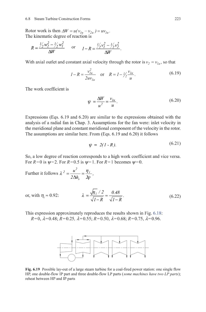
Fig. 6.19 Possible lay-out of a large steam turbine for a coal-fired power station: one single flow
HP, one double-flow IP part and three double-flow LP parts ( some machines have two LP parts);
reheat between HP and IP parts
6.8 Steam Turbine Construction Forms
Rotor work is then ∆W u v
v
uv
u
u
u
=
−
=
(
)
.
1
2
1
The kinematic degree of reaction is
2
2
1
1
2
1
2
2
w
w
R
W
−
=
D
or
2
2
1
1
1
2
2
2
v
v
1 R
.
W
D
−
− =
With axial outlet and constant axial velocity through the rotor is v v a
2
1
=
, so that
1
2
1
1
2
1
1 2
1
− =
= −
R
v
uv
R
v
u
u
u
u
or
.
(6.19)
The work coefficient is
1u
2
v
W
.
u
u
=
=
D
y
(6.20)
Expressions (Eqs. 6.19 and 6.20) are similar to the expressions obtained with the
analysis of a radial fan in Chap. 3. Assumptions for the fan were: inlet velocity in
the meridional plane and constant meridional component of the velocity in the rotor.
The assumptions are similar here. From (Eqs. 6.19 and 6.20) it follows
(6.21)
So, a low degree of reaction corresponds to a high work coefficient and vice versa.
For R = 0 is y = 2. For R = 0.5 is y = 1. For R = 1 becomes y = 0.
Further it follows
2
2
i
s
u
,
2 h
2
=
=
h
l
D
y
or, with h i ≈ 0.92:
(6.22)
This expression approximately reproduces the results shown in Fig. 6.18:
R = 0, l = 0.48; R = 0.25, l = 0.55; R = 0.50, l = 0.68; R = 0.75, l = 0.96.
-
2( 1 R ).
=
y
i / 2
0.48 .
1 R
1 R
=
≈
−
−
h
l
Fig. 6.19 Possible lay-out of a large steam turbine for a coal-fired power station: one single flow
HP, one double-flow IP part and three double-flow LP parts ( some machines have two LP parts);
reheat between HP and IP parts