

215
6.6 The Velocity-Compounded Impulse Turbine or Curtis Turbine
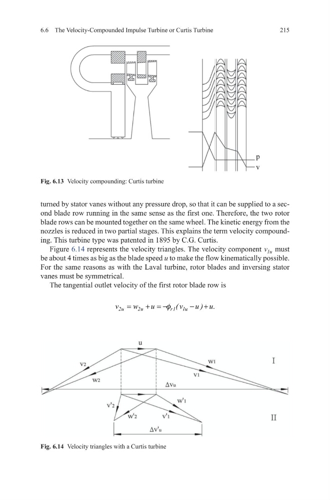
turned by stator vanes without any pressure drop, so that it can be supplied to a second blade row running in the same sense as the first one. Therefore, the two rotor
blade rows can be mounted together on the same wheel. The kinetic energy from the
nozzles is reduced in two partial stages. This explains the term velocity compounding. This turbine type was patented in 1895 by C.G. Curtis.
Figure 6.14 represents the velocity triangles. The velocity component v u
1 must
be about 4 times as big as the blade speed u to make the flow kinematically possible.
For the same reasons as with the Laval turbine, rotor blades and inversing stator
vanes must be symmetrical.
The tangential outlet velocity of the first rotor blade row is
2u
2u
r1 1u
v
w
u
( v
u ) u.
=
+ = −
− +
f
Fig. 6.13 Velocity compounding: Curtis turbine
Fig. 6.14 Velocity triangles with a Curtis turbine
6.6 The Velocity-Compounded Impulse Turbine or Curtis Turbine
turned by stator vanes without any pressure drop, so that it can be supplied to a second blade row running in the same sense as the first one. Therefore, the two rotor
blade rows can be mounted together on the same wheel. The kinetic energy from the
nozzles is reduced in two partial stages. This explains the term velocity compounding. This turbine type was patented in 1895 by C.G. Curtis.
Figure 6.14 represents the velocity triangles. The velocity component v u
1 must
be about 4 times as big as the blade speed u to make the flow kinematically possible.
For the same reasons as with the Laval turbine, rotor blades and inversing stator
vanes must be symmetrical.
The tangential outlet velocity of the first rotor blade row is
2u
2u
r1 1u
v
w
u
( v
u ) u.
=
+ = −
− +
f
Fig. 6.13 Velocity compounding: Curtis turbine
Fig. 6.14 Velocity triangles with a Curtis turbine