

214
6 Steam Turbines
The optimum speed ratio changes onto a much higher value compared to optimisation with outlet kinetic energy loss: from 0.47 to 0.72, but the meaning of the
reference velocity v s is not the same in both cases. With equal pressure levels, v s
is lower here. This partially explains the higher value of l. The ratio of the outlet
kinetic energy to the enthalpy drop is about 25 % with l = 0.72. Thus, this difference cannot be the only cause of a much higher speed ratio at optimum efficiency.
The efficiency is almost 9 percentage points better: it increases from 84 % to almost
93 %. The efficiency increase comes from the outlet kinetic energy recovery. The
optimum speed ratio shifts to a higher value, since rotor and stator turnings then decrease, and the loss coefficients with them. The outlet kinetic energy increases, but
this is not a penalisation now. For the same reason, the nozzle outlet angle does not
have to take the maximum technically realisable value. We assume here the rather
high value of a 1 = 75°, because this leads to low axial velocity and hence large
height of the blades. This is appropriate for flow with high steam density as in the
high-pressure part of the turbine. But actually, the nozzle angle may be optimised
too (see Chap. 15). The optimum as a function of speed ratio is very weak so that
the speed ratio may be strongly reduced without significant reduction of the internal
efficiency. The efficiency decreases with about one and a half percentage point with
a speed ratio lowered until 0.54. The work coefficient is higher with a lower speed
ratio. The turbine may then be built with fewer stages, which results in lower disc
friction loss. The consequence is that the speed ratio for optimum overall efficiency
(leakage and disc friction included) is much lower than that for optimum internal
efficiency. The foregoing argumentation does not allow the determination of the
precise value of the optimum speed ratio. We may assume that it is around 0.54. The
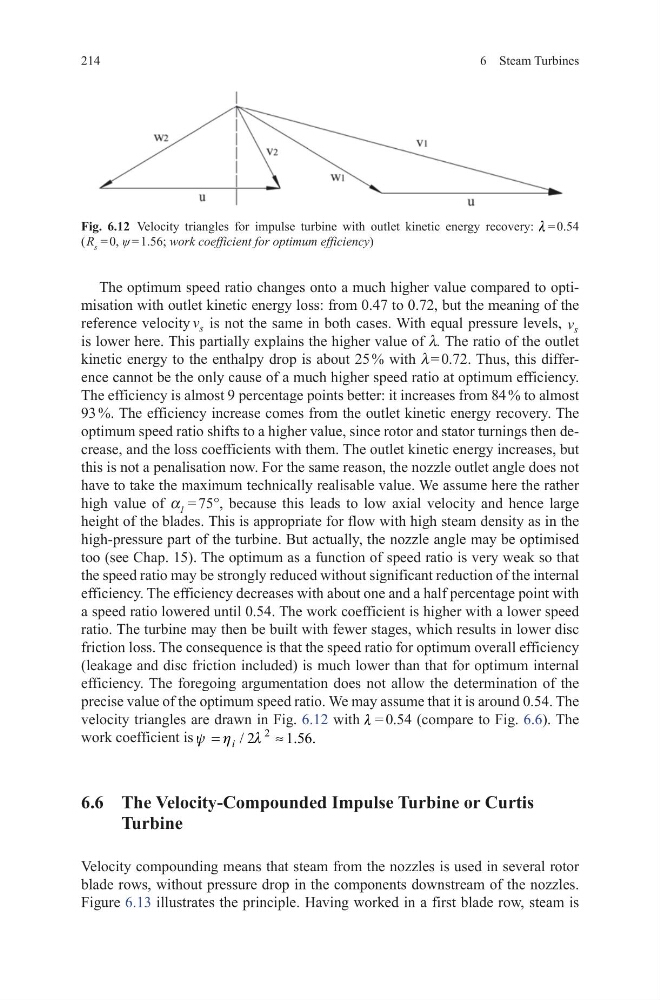
velocity triangles are drawn in Fig. 6.12 with l = 0.54 (compare to Fig. 6.6). The
work coefficient is
2
/ 2
1.56.
i
y h
l
=
≈
6.6 The Velocity-Compounded Impulse Turbine or Curtis
Turbine
Velocity compounding means that steam from the nozzles is used in several rotor
blade rows, without pressure drop in the components downstream of the nozzles.
Figure 6.13 illustrates the principle. Having worked in a first blade row, steam is
Fig. 6.12 Velocity triangles for impulse turbine with outlet kinetic energy recovery: l = 0.54
( R s = 0, ψ = 1.56; work coefficient for optimum efficiency)
6 Steam Turbines
The optimum speed ratio changes onto a much higher value compared to optimisation with outlet kinetic energy loss: from 0.47 to 0.72, but the meaning of the
reference velocity v s is not the same in both cases. With equal pressure levels, v s
is lower here. This partially explains the higher value of l. The ratio of the outlet
kinetic energy to the enthalpy drop is about 25 % with l = 0.72. Thus, this difference cannot be the only cause of a much higher speed ratio at optimum efficiency.
The efficiency is almost 9 percentage points better: it increases from 84 % to almost
93 %. The efficiency increase comes from the outlet kinetic energy recovery. The
optimum speed ratio shifts to a higher value, since rotor and stator turnings then decrease, and the loss coefficients with them. The outlet kinetic energy increases, but
this is not a penalisation now. For the same reason, the nozzle outlet angle does not
have to take the maximum technically realisable value. We assume here the rather
high value of a 1 = 75°, because this leads to low axial velocity and hence large
height of the blades. This is appropriate for flow with high steam density as in the
high-pressure part of the turbine. But actually, the nozzle angle may be optimised
too (see Chap. 15). The optimum as a function of speed ratio is very weak so that
the speed ratio may be strongly reduced without significant reduction of the internal
efficiency. The efficiency decreases with about one and a half percentage point with
a speed ratio lowered until 0.54. The work coefficient is higher with a lower speed
ratio. The turbine may then be built with fewer stages, which results in lower disc
friction loss. The consequence is that the speed ratio for optimum overall efficiency
(leakage and disc friction included) is much lower than that for optimum internal
efficiency. The foregoing argumentation does not allow the determination of the
precise value of the optimum speed ratio. We may assume that it is around 0.54. The
velocity triangles are drawn in Fig. 6.12 with l = 0.54 (compare to Fig. 6.6). The
work coefficient is
2
/ 2
1.56.
i
y h
l
=
≈
6.6 The Velocity-Compounded Impulse Turbine or Curtis
Turbine
Velocity compounding means that steam from the nozzles is used in several rotor
blade rows, without pressure drop in the components downstream of the nozzles.
Figure 6.13 illustrates the principle. Having worked in a first blade row, steam is
Fig. 6.12 Velocity triangles for impulse turbine with outlet kinetic energy recovery: l = 0.54
( R s = 0, ψ = 1.56; work coefficient for optimum efficiency)