

213
6.5 The Pressure-Compounded Impulse Turbine or Rateau Turbine
6.5.2 Efficiency
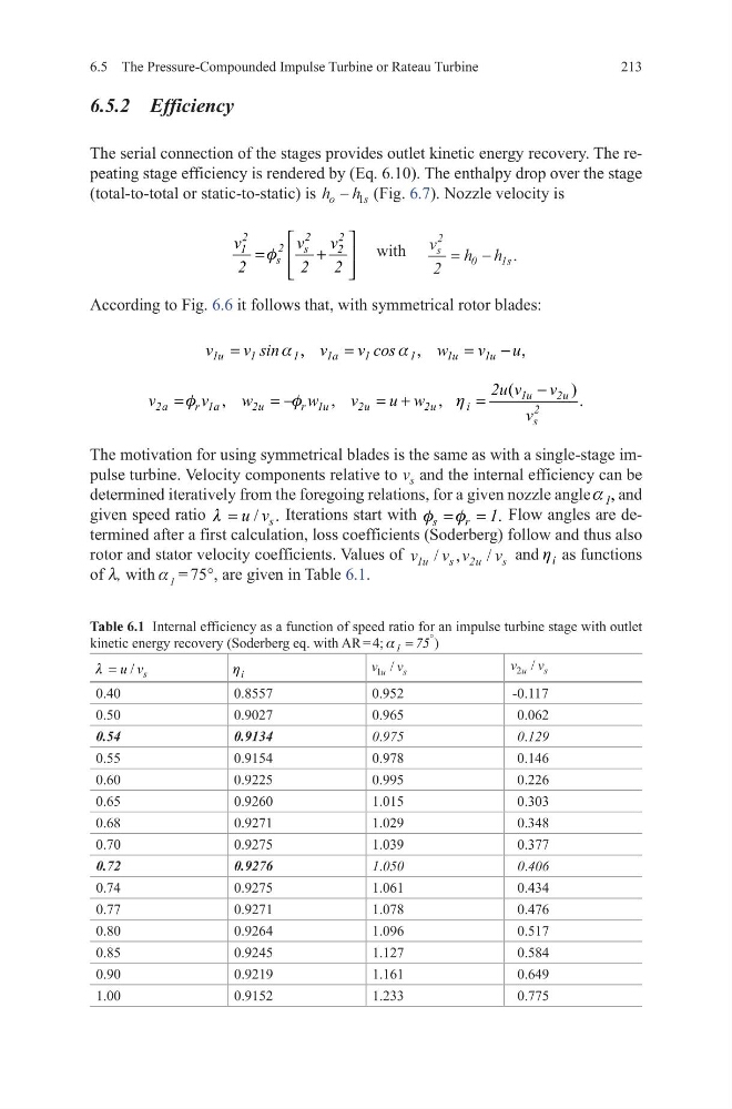
The serial connection of the stages provides outlet kinetic energy recovery. The repeating stage efficiency is rendered by (Eq. 6.10). The enthalpy drop over the stage
(total-to-total or static-to-static) is h h
o
s
− 1 (Fig. 6.7). Nozzle velocity is
2
2
2
2
s
1
2
s
v
v
v
2
2
2
f
=
+
with v
h h
s
s
2
0
1
2
= − .
According to Fig. 6.6 it follows that, with symmetrical rotor blades:
The motivation for using symmetrical blades is the same as with a single-stage impulse turbine. Velocity components relative to v s and the internal efficiency can be
determined iteratively from the foregoing relations, for a given nozzle angle ,
1
a and
given speed ratio
/ .
s
u v
l =
Iterations start with
.
s
r
1
f f
= = Flow angles are determined after a first calculation, loss coefficients (Soderberg) follow and thus also
rotor and stator velocity coefficients. Values of v v v
v
u
s
u
s
1
2
/ ,
/ and i
h as functions
of l, with a 1 = 75°, are given in Table 6.1.
,
,
,
1u
1
1
1a
1
1
1u
1u
v
v sin
v
v cos
w
v
u
a
a
=
=
=
−
(
)
,
,
,
.
1u
2u
2a
r 1a
2u
r 1u
2u
2u
i
2
s
2u v
v
v
v
w
w
v
u w
v
f
f
h
−
=
= −
= +
=
Table 6.1 Internal efficiency as a function of speed ratio for an impulse turbine stage with outlet
kinetic energy recovery (Soderberg eq. with AR = 4; 1 75
°
=
a
)
/ s
u v
l =
i
h
v v
u
s
1 /
v v
u
s
2 /
0.40
0.8557
0.952
-0.117
0.50
0.9027
0.965
0.062
0.54
0.9134
0.975
0.129
0.55
0.9154
0.978
0.146
0.60
0.9225
0.995
0.226
0.65
0.9260
1.015
0.303
0.68
0.9271
1.029
0.348
0.70
0.9275
1.039
0.377
0.72
0.9276
1.050
0.406
0.74
0.9275
1.061
0.434
0.77
0.9271
1.078
0.476
0.80
0.9264
1.096
0.517
0.85
0.9245
1.127
0.584
0.90
0.9219
1.161
0.649
1.00
0.9152
1.233
0.775
6.5 The Pressure-Compounded Impulse Turbine or Rateau Turbine
6.5.2 Efficiency
The serial connection of the stages provides outlet kinetic energy recovery. The repeating stage efficiency is rendered by (Eq. 6.10). The enthalpy drop over the stage
(total-to-total or static-to-static) is h h
o
s
− 1 (Fig. 6.7). Nozzle velocity is
2
2
2
2
s
1
2
s
v
v
v
2
2
2
f
=
+
with v
h h
s
s
2
0
1
2
= − .
According to Fig. 6.6 it follows that, with symmetrical rotor blades:
The motivation for using symmetrical blades is the same as with a single-stage impulse turbine. Velocity components relative to v s and the internal efficiency can be
determined iteratively from the foregoing relations, for a given nozzle angle ,
1
a and
given speed ratio
/ .
s
u v
l =
Iterations start with
.
s
r
1
f f
= = Flow angles are determined after a first calculation, loss coefficients (Soderberg) follow and thus also
rotor and stator velocity coefficients. Values of v v v
v
u
s
u
s
1
2
/ ,
/ and i
h as functions
of l, with a 1 = 75°, are given in Table 6.1.
,
,
,
1u
1
1
1a
1
1
1u
1u
v
v sin
v
v cos
w
v
u
a
a
=
=
=
−
(
)
,
,
,
.
1u
2u
2a
r 1a
2u
r 1u
2u
2u
i
2
s
2u v
v
v
v
w
w
v
u w
v
f
f
h
−
=
= −
= +
=
Table 6.1 Internal efficiency as a function of speed ratio for an impulse turbine stage with outlet
kinetic energy recovery (Soderberg eq. with AR = 4; 1 75
°
=
a
)
/ s
u v
l =
i
h
v v
u
s
1 /
v v
u
s
2 /
0.40
0.8557
0.952
-0.117
0.50
0.9027
0.965
0.062
0.54
0.9134
0.975
0.129
0.55
0.9154
0.978
0.146
0.60
0.9225
0.995
0.226
0.65
0.9260
1.015
0.303
0.68
0.9271
1.029
0.348
0.70
0.9275
1.039
0.377
0.72
0.9276
1.050
0.406
0.74
0.9275
1.061
0.434
0.77
0.9271
1.078
0.476
0.80
0.9264
1.096
0.517
0.85
0.9245
1.127
0.584
0.90
0.9219
1.161
0.649
1.00
0.9152
1.233
0.775