

207
6.4 The Single Impulse Stage or Laval Stage
centre O’. Suction side parts EC and DF are drawn straight in the figure, parallel
with the inlet and outlet flow directions. The flow in the channel part A’B’CD has
circular streamlines with centre O’. Thus, in absence of losses, the flow satisfies the
free-vortex law with constant angular momentum around the centre O’. This means
that the streamline A’B’ is under constant pressure, namely inlet pressure and outlet
pressure. The CD part is under constant pressure as well, but at a lower value than
the common inlet and outlet pressure. Pressure decreases in flow direction in the EC
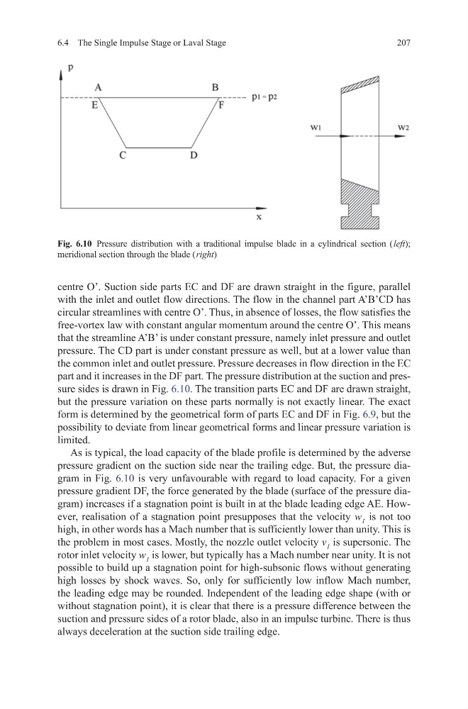
part and it increases in the DF part. The pressure distribution at the suction and pressure sides is drawn in Fig. 6.10. The transition parts EC and DF are drawn straight,
but the pressure variation on these parts normally is not exactly linear. The exact
form is determined by the geometrical form of parts EC and DF in Fig. 6.9, but the
possibility to deviate from linear geometrical forms and linear pressure variation is
limited.
As is typical, the load capacity of the blade profile is determined by the adverse
pressure gradient on the suction side near the trailing edge. But, the pressure diagram in Fig. 6.10 is very unfavourable with regard to load capacity. For a given
pressure gradient DF, the force generated by the blade (surface of the pressure diagram) increases if a stagnation point is built in at the blade leading edge AE. However, realisation of a stagnation point presupposes that the velocity w 1 is not too
high, in other words has a Mach number that is sufficiently lower than unity. This is
the problem in most cases. Mostly, the nozzle outlet velocity v 1 is supersonic. The
rotor inlet velocity w 1 is lower, but typically has a Mach number near unity. It is not
possible to build up a stagnation point for high-subsonic flows without generating
high losses by shock waves. So, only for sufficiently low inflow Mach number,
the leading edge may be rounded. Independent of the leading edge shape (with or
without stagnation point), it is clear that there is a pressure difference between the
suction and pressure sides of a rotor blade, also in an impulse turbine. There is thus
always deceleration at the suction side trailing edge.
Fig. 6.10 Pressure distribution with a traditional impulse blade in a cylindrical section ( left);
meridional section through the blade ( right)
6.4 The Single Impulse Stage or Laval Stage
centre O’. Suction side parts EC and DF are drawn straight in the figure, parallel
with the inlet and outlet flow directions. The flow in the channel part A’B’CD has
circular streamlines with centre O’. Thus, in absence of losses, the flow satisfies the
free-vortex law with constant angular momentum around the centre O’. This means
that the streamline A’B’ is under constant pressure, namely inlet pressure and outlet
pressure. The CD part is under constant pressure as well, but at a lower value than
the common inlet and outlet pressure. Pressure decreases in flow direction in the EC
part and it increases in the DF part. The pressure distribution at the suction and pressure sides is drawn in Fig. 6.10. The transition parts EC and DF are drawn straight,
but the pressure variation on these parts normally is not exactly linear. The exact
form is determined by the geometrical form of parts EC and DF in Fig. 6.9, but the
possibility to deviate from linear geometrical forms and linear pressure variation is
limited.
As is typical, the load capacity of the blade profile is determined by the adverse
pressure gradient on the suction side near the trailing edge. But, the pressure diagram in Fig. 6.10 is very unfavourable with regard to load capacity. For a given
pressure gradient DF, the force generated by the blade (surface of the pressure diagram) increases if a stagnation point is built in at the blade leading edge AE. However, realisation of a stagnation point presupposes that the velocity w 1 is not too
high, in other words has a Mach number that is sufficiently lower than unity. This is
the problem in most cases. Mostly, the nozzle outlet velocity v 1 is supersonic. The
rotor inlet velocity w 1 is lower, but typically has a Mach number near unity. It is not
possible to build up a stagnation point for high-subsonic flows without generating
high losses by shock waves. So, only for sufficiently low inflow Mach number,
the leading edge may be rounded. Independent of the leading edge shape (with or
without stagnation point), it is clear that there is a pressure difference between the
suction and pressure sides of a rotor blade, also in an impulse turbine. There is thus
always deceleration at the suction side trailing edge.
Fig. 6.10 Pressure distribution with a traditional impulse blade in a cylindrical section ( left);
meridional section through the blade ( right)