

206
6 Steam Turbines
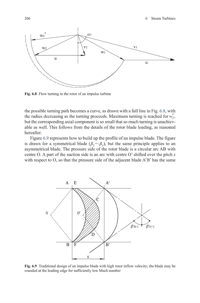
the possible turning path becomes a curve, as drawn with a full line in Fig. 6.8, with
the radius decreasing as the turning proceeds. Maximum turning is reached for w 2
*
,
but the corresponding axial component is so small that so much turning is unachievable as well. This follows from the details of the rotor blade loading, as reasoned
hereafter.
Figure 6.9 represents how to build up the profile of an impulse blade. The figure
is drawn for a symmetrical blade ( β 2 = -β 1 ), but the same principle applies to an
asymmetrical blade. The pressure side of the rotor blade is a circular arc AB with
centre O. A part of the suction side is an arc with centre O’ shifted over the pitch s
with respect to O, so that the pressure side of the adjacent blade A’B’ has the same
Fig. 6.9 Traditional design of an impulse blade with high rotor inflow velocity; the blade may be
rounded at the leading edge for sufficiently low Mach number
Fig. 6.8 Flow turning in the rotor of an impulse turbine
6 Steam Turbines
the possible turning path becomes a curve, as drawn with a full line in Fig. 6.8, with
the radius decreasing as the turning proceeds. Maximum turning is reached for w 2
*
,
but the corresponding axial component is so small that so much turning is unachievable as well. This follows from the details of the rotor blade loading, as reasoned
hereafter.
Figure 6.9 represents how to build up the profile of an impulse blade. The figure
is drawn for a symmetrical blade ( β 2 = -β 1 ), but the same principle applies to an
asymmetrical blade. The pressure side of the rotor blade is a circular arc AB with
centre O. A part of the suction side is an arc with centre O’ shifted over the pitch s
with respect to O, so that the pressure side of the adjacent blade A’B’ has the same
Fig. 6.9 Traditional design of an impulse blade with high rotor inflow velocity; the blade may be
rounded at the leading edge for sufficiently low Mach number
Fig. 6.8 Flow turning in the rotor of an impulse turbine