

197
6.2 Working Principles of Steam Turbines
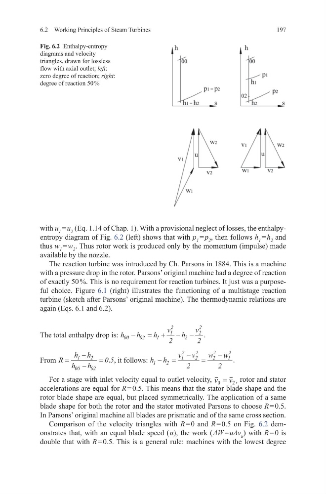
with u 1 = u 2 (Eq. 1.14 of Chap. 1). With a provisional neglect of losses, the enthalpyentropy diagram of Fig. 6.2 (left) shows that with p 1 = p 2 , then follows h 1 = h 2 and
thus w 1 = w 2 . Thus rotor work is produced only by the momentum (impulse) made
available by the nozzle.
The reaction turbine was introduced by Ch. Parsons in 1884. This is a machine
with a pressure drop in the rotor. Parsons’ original machine had a degree of reaction
of exactly 50 %. This is no requirement for reaction turbines. It just was a purposeful choice. Figure 6.1 (right) illustrates the functioning of a multistage reaction
turbine (sketch after Parsons’ original machine). The thermodynamic relations are
again (Eqs. 6.1 and 6.2).
The total enthalpy drop is: h
h
h
v h
v
00
02
1
1
2
2
2
2
2
2
−
= + − − .
From R
h h
h
h
=
−
−
=
1
2
00
02
0 5
. , it follows: h h
v v
w w
1
2
1
2
2
2
2
2
1
2
2
2
− =
− =
− .
For a stage with inlet velocity equal to outlet velocity,
v v
0
2
= , rotor and stator
accelerations are equal for R = 0.5. This means that the stator blade shape and the
rotor blade shape are equal, but placed symmetrically. The application of a same
blade shape for both the rotor and the stator motivated Parsons to choose R = 0.5.
In Parsons’ original machine all blades are prismatic and of the same cross section.
Comparison of the velocity triangles with R = 0 and R = 0.5 on Fig. 6.2 demonstrates that, with an equal blade speed ( u), the work ( ΔW = uΔv u ) with R = 0 is
double that with R = 0.5. This is a general rule: machines with the lowest degree
Fig. 6.2 Enthalpy-entropy
diagrams and velocity
triangles, drawn for lossless
flow with axial outlet; left:
zero degree of reaction; right:
degree of reaction 50 %
6.2 Working Principles of Steam Turbines
with u 1 = u 2 (Eq. 1.14 of Chap. 1). With a provisional neglect of losses, the enthalpyentropy diagram of Fig. 6.2 (left) shows that with p 1 = p 2 , then follows h 1 = h 2 and
thus w 1 = w 2 . Thus rotor work is produced only by the momentum (impulse) made
available by the nozzle.
The reaction turbine was introduced by Ch. Parsons in 1884. This is a machine
with a pressure drop in the rotor. Parsons’ original machine had a degree of reaction
of exactly 50 %. This is no requirement for reaction turbines. It just was a purposeful choice. Figure 6.1 (right) illustrates the functioning of a multistage reaction
turbine (sketch after Parsons’ original machine). The thermodynamic relations are
again (Eqs. 6.1 and 6.2).
The total enthalpy drop is: h
h
h
v h
v
00
02
1
1
2
2
2
2
2
2
−
= + − − .
From R
h h
h
h
=
−
−
=
1
2
00
02
0 5
. , it follows: h h
v v
w w
1
2
1
2
2
2
2
2
1
2
2
2
− =
− =
− .
For a stage with inlet velocity equal to outlet velocity,
v v
0
2
= , rotor and stator
accelerations are equal for R = 0.5. This means that the stator blade shape and the
rotor blade shape are equal, but placed symmetrically. The application of a same
blade shape for both the rotor and the stator motivated Parsons to choose R = 0.5.
In Parsons’ original machine all blades are prismatic and of the same cross section.
Comparison of the velocity triangles with R = 0 and R = 0.5 on Fig. 6.2 demonstrates that, with an equal blade speed ( u), the work ( ΔW = uΔv u ) with R = 0 is
double that with R = 0.5. This is a general rule: machines with the lowest degree
Fig. 6.2 Enthalpy-entropy
diagrams and velocity
triangles, drawn for lossless
flow with axial outlet; left:
zero degree of reaction; right:
degree of reaction 50 %