

3.5 Overall Performance Evaluation
135
3.5.2 Leakage Loss
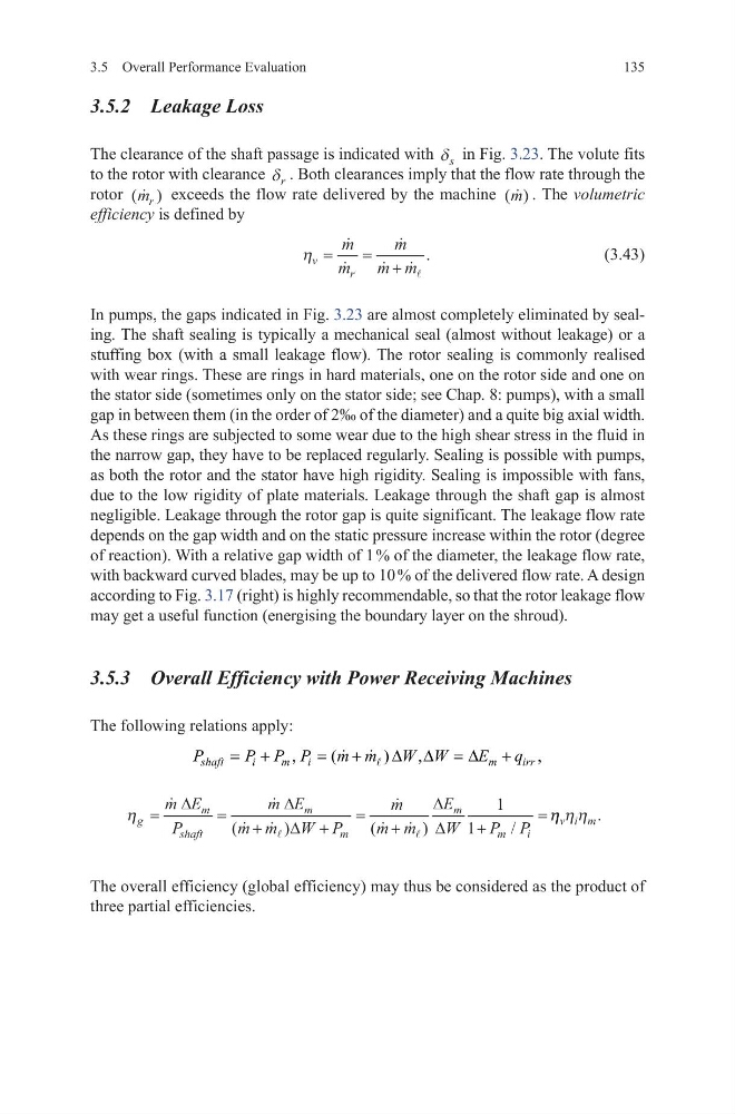
The clearance of the shaft passage is indicated with δ s in Fig. 3.23. The volute fits
to the rotor with clearance δ r . Both clearances imply that the flow rate through the
rotor ( )
m r exceeds the flow rate delivered by the machine ( )
m . The volumetric
efficiency is defined by
(3.43)
In pumps, the gaps indicated in Fig. 3.23 are almost completely eliminated by sealing. The shaft sealing is typically a mechanical seal (almost without leakage) or a
stuffing box (with a small leakage flow). The rotor sealing is commonly realised
with wear rings. These are rings in hard materials, one on the rotor side and one on
the stator side (sometimes only on the stator side; see Chap. 8: pumps), with a small
gap in between them (in the order of 2‰ of the diameter) and a quite big axial width.
As these rings are subjected to some wear due to the high shear stress in the fluid in
the narrow gap, they have to be replaced regularly. Sealing is possible with pumps,
as both the rotor and the stator have high rigidity. Sealing is impossible with fans,
due to the low rigidity of plate materials. Leakage through the shaft gap is almost
negligible. Leakage through the rotor gap is quite significant. The leakage flow rate
depends on the gap width and on the static pressure increase within the rotor (degree
of reaction). With a relative gap width of 1 % of the diameter, the leakage flow rate,
with backward curved blades, may be up to 10 % of the delivered flow rate. A design
according to Fig. 3.17 (right) is highly recommendable, so that the rotor leakage flow
may get a useful function (energising the boundary layer on the shroud).
3.5.3 Overall Efficiency with Power Receiving Machines
The following relations apply:
The overall efficiency (global efficiency) may thus be considered as the product of
three partial efficiencies.
η v
r
m
m
m
m m
=
= +
.
,
(
)
,
,
shaft
i
m
i
m
irr
P
P P P
m m
W W
E
q
= +
=
+
∆ ∆ = ∆ +
η g
m
shaft
m
m
m
m
i
m E
P
m E
m m W P
m
m m
E
W
P P
=
=
+
+
=
+
+
=
∆
∆
∆
∆
∆
(
)
(
)
/
1
1
η η η η
v i m .
135
3.5.2 Leakage Loss
The clearance of the shaft passage is indicated with δ s in Fig. 3.23. The volute fits
to the rotor with clearance δ r . Both clearances imply that the flow rate through the
rotor ( )
m r exceeds the flow rate delivered by the machine ( )
m . The volumetric
efficiency is defined by
(3.43)
In pumps, the gaps indicated in Fig. 3.23 are almost completely eliminated by sealing. The shaft sealing is typically a mechanical seal (almost without leakage) or a
stuffing box (with a small leakage flow). The rotor sealing is commonly realised
with wear rings. These are rings in hard materials, one on the rotor side and one on
the stator side (sometimes only on the stator side; see Chap. 8: pumps), with a small
gap in between them (in the order of 2‰ of the diameter) and a quite big axial width.
As these rings are subjected to some wear due to the high shear stress in the fluid in
the narrow gap, they have to be replaced regularly. Sealing is possible with pumps,
as both the rotor and the stator have high rigidity. Sealing is impossible with fans,
due to the low rigidity of plate materials. Leakage through the shaft gap is almost
negligible. Leakage through the rotor gap is quite significant. The leakage flow rate
depends on the gap width and on the static pressure increase within the rotor (degree
of reaction). With a relative gap width of 1 % of the diameter, the leakage flow rate,
with backward curved blades, may be up to 10 % of the delivered flow rate. A design
according to Fig. 3.17 (right) is highly recommendable, so that the rotor leakage flow
may get a useful function (energising the boundary layer on the shroud).
3.5.3 Overall Efficiency with Power Receiving Machines
The following relations apply:
The overall efficiency (global efficiency) may thus be considered as the product of
three partial efficiencies.
η v
r
m
m
m
m m
=
= +
.
,
(
)
,
,
shaft
i
m
i
m
irr
P
P P P
m m
W W
E
q
= +
=
+
∆ ∆ = ∆ +
η g
m
shaft
m
m
m
m
i
m E
P
m E
m m W P
m
m m
E
W
P P
=
=
+
+
=
+
+
=
∆
∆
∆
∆
∆
(
)
(
)
/
1
1
η η η η
v i m .