

124
3 Fans
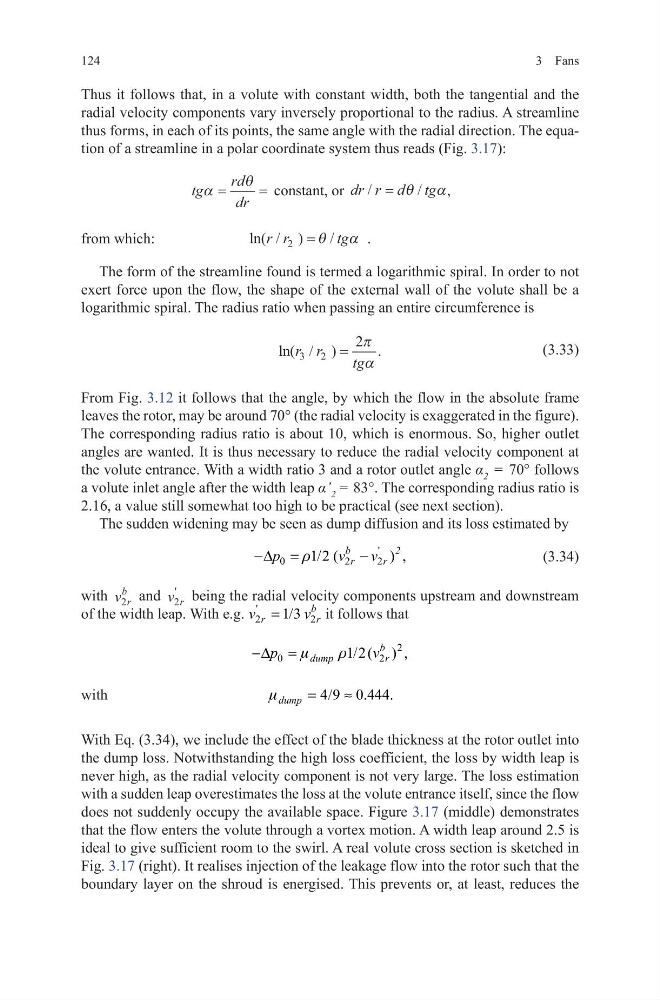
Thus it follows that, in a volute with constant width, both the tangential and the
radial velocity components vary inversely proportional to the radius. A streamline
thus forms, in each of its points, the same angle with the radial direction. The equation of a streamline in a polar coordinate system thus reads (Fig. 3.17):
tg
rd
dr
α
θ
=
= constant, or dr r d tg
/
/
= θ
α,
from which:
ln( / )
/
r r
tg
2 = θ
α .
The form of the streamline found is termed a logarithmic spiral. In order to not
exert force upon the flow, the shape of the external wall of the volute shall be a
logarithmic spiral. The radius ratio when passing an entire circumference is
(3.33)
From Fig. 3.12 it follows that the angle, by which the flow in the absolute frame
leaves the rotor, may be around 70° (the radial velocity is exaggerated in the figure).
The corresponding radius ratio is about 10, which is enormous. So, higher outlet
angles are wanted. It is thus necessary to reduce the radial velocity component at
the volute entrance. With a width ratio 3 and a rotor outlet angle α 2 = 70° follows
a volute inlet angle after the width leap α’ 2 = 83°. The corresponding radius ratio is
2.16, a value still somewhat too high to be practical (see next section).
The sudden widening may be seen as dump diffusion and its loss estimated by
(3.34)
with v r
b
2 and v r
2
'
being the radial velocity components upstream and downstream
of the width leap. With e.g.
'
2
2
1/3
b
r
r
v
v
=
it follows that
with
With Eq. (3.34), we include the effect of the blade thickness at the rotor outlet into
the dump loss. Notwithstanding the high loss coefficient, the loss by width leap is
never high, as the radial velocity component is not very large. The loss estimation
with a sudden leap overestimates the loss at the volute entrance itself, since the flow
does not suddenly occupy the available space. Figure 3.17 (middle) demonstrates
that the flow enters the volute through a vortex motion. A width leap around 2.5 is
ideal to give sufficient room to the swirl. A real volute cross section is sketched in
Fig. 3.17 (right). It realises injection of the leakage flow into the rotor such that the
boundary layer on the shroud is energised. This prevents or, at least, reduces the
ln( / )
.
r r
tg
3
2
2
=
π
α
'
0
2
2
1/2 (
) ,
b
2
r
r
p
v
v
r
−∆ =
−
2
0
2
1/2 ( ) ,
b
dump
r
p
v
m
r
−∆ =
4/9 0.444.
dump
m
=
≈
3 Fans
Thus it follows that, in a volute with constant width, both the tangential and the
radial velocity components vary inversely proportional to the radius. A streamline
thus forms, in each of its points, the same angle with the radial direction. The equation of a streamline in a polar coordinate system thus reads (Fig. 3.17):
tg
rd
dr
α
θ
=
= constant, or dr r d tg
/
/
= θ
α,
from which:
ln( / )
/
r r
tg
2 = θ
α .
The form of the streamline found is termed a logarithmic spiral. In order to not
exert force upon the flow, the shape of the external wall of the volute shall be a
logarithmic spiral. The radius ratio when passing an entire circumference is
(3.33)
From Fig. 3.12 it follows that the angle, by which the flow in the absolute frame
leaves the rotor, may be around 70° (the radial velocity is exaggerated in the figure).
The corresponding radius ratio is about 10, which is enormous. So, higher outlet
angles are wanted. It is thus necessary to reduce the radial velocity component at
the volute entrance. With a width ratio 3 and a rotor outlet angle α 2 = 70° follows
a volute inlet angle after the width leap α’ 2 = 83°. The corresponding radius ratio is
2.16, a value still somewhat too high to be practical (see next section).
The sudden widening may be seen as dump diffusion and its loss estimated by
(3.34)
with v r
b
2 and v r
2
'
being the radial velocity components upstream and downstream
of the width leap. With e.g.
'
2
2
1/3
b
r
r
v
v
=
it follows that
with
With Eq. (3.34), we include the effect of the blade thickness at the rotor outlet into
the dump loss. Notwithstanding the high loss coefficient, the loss by width leap is
never high, as the radial velocity component is not very large. The loss estimation
with a sudden leap overestimates the loss at the volute entrance itself, since the flow
does not suddenly occupy the available space. Figure 3.17 (middle) demonstrates
that the flow enters the volute through a vortex motion. A width leap around 2.5 is
ideal to give sufficient room to the swirl. A real volute cross section is sketched in
Fig. 3.17 (right). It realises injection of the leakage flow into the rotor such that the
boundary layer on the shroud is energised. This prevents or, at least, reduces the
ln( / )
.
r r
tg
3
2
2
=
π
α
'
0
2
2
1/2 (
) ,
b
2
r
r
p
v
v
r
−∆ =
−
2
0
2
1/2 ( ) ,
b
dump
r
p
v
m
r
−∆ =
4/9 0.444.
dump
m
=
≈