

3.4 Internal Losses with Radial Fans
125
separation of the inlet flow, which has to turn 90°. The boundary layer that would
separate without the injection is sucked to the wall by momentum transfer from the
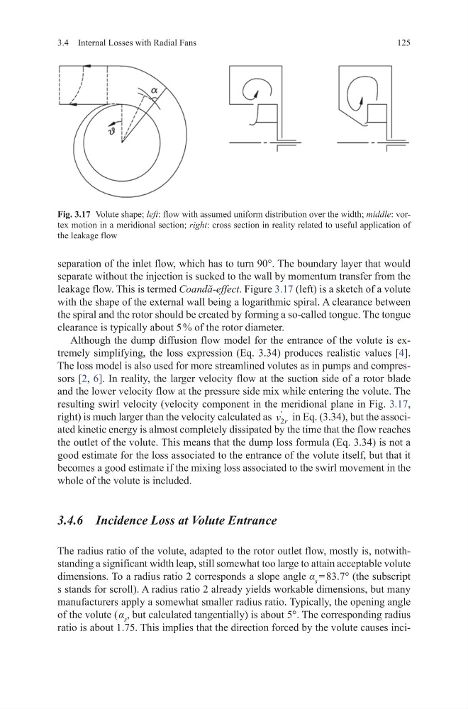
leakage flow. This is termed Coandă-effect. Figure 3.17 (left) is a sketch of a volute
with the shape of the external wall being a logarithmic spiral. A clearance between
the spiral and the rotor should be created by forming a so-called tongue. The tongue
clearance is typically about 5 % of the rotor diameter.
Although the dump diffusion flow model for the entrance of the volute is extremely simplifying, the loss expression (Eq. 3.34) produces realistic values [4].
The loss model is also used for more streamlined volutes as in pumps and compressors [2, 6]. In reality, the larger velocity flow at the suction side of a rotor blade
and the lower velocity flow at the pressure side mix while entering the volute. The
resulting swirl velocity (velocity component in the meridional plane in Fig. 3.17,
right) is much larger than the velocity calculated as v r
2
'
in Eq. (3.34), but the associated kinetic energy is almost completely dissipated by the time that the flow reaches
the outlet of the volute. This means that the dump loss formula (Eq. 3.34) is not a
good estimate for the loss associated to the entrance of the volute itself, but that it
becomes a good estimate if the mixing loss associated to the swirl movement in the
whole of the volute is included.
3.4.6 Incidence Loss at Volute Entrance
The radius ratio of the volute, adapted to the rotor outlet flow, mostly is, notwithstanding a significant width leap, still somewhat too large to attain acceptable volute
dimensions. To a radius ratio 2 corresponds a slope angle α s = 83.7° (the subscript
s stands for scroll). A radius ratio 2 already yields workable dimensions, but many
manufacturers apply a somewhat smaller radius ratio. Typically, the opening angle
of the volute ( α s , but calculated tangentially) is about 5°. The corresponding radius
ratio is about 1.75. This implies that the direction forced by the volute causes inciFig. 3.17 Volute shape; left: flow with assumed uniform distribution over the width; middle: vortex motion in a meridional section; right: cross section in reality related to useful application of
the leakage flow
125
separation of the inlet flow, which has to turn 90°. The boundary layer that would
separate without the injection is sucked to the wall by momentum transfer from the
leakage flow. This is termed Coandă-effect. Figure 3.17 (left) is a sketch of a volute
with the shape of the external wall being a logarithmic spiral. A clearance between
the spiral and the rotor should be created by forming a so-called tongue. The tongue
clearance is typically about 5 % of the rotor diameter.
Although the dump diffusion flow model for the entrance of the volute is extremely simplifying, the loss expression (Eq. 3.34) produces realistic values [4].
The loss model is also used for more streamlined volutes as in pumps and compressors [2, 6]. In reality, the larger velocity flow at the suction side of a rotor blade
and the lower velocity flow at the pressure side mix while entering the volute. The
resulting swirl velocity (velocity component in the meridional plane in Fig. 3.17,
right) is much larger than the velocity calculated as v r
2
'
in Eq. (3.34), but the associated kinetic energy is almost completely dissipated by the time that the flow reaches
the outlet of the volute. This means that the dump loss formula (Eq. 3.34) is not a
good estimate for the loss associated to the entrance of the volute itself, but that it
becomes a good estimate if the mixing loss associated to the swirl movement in the
whole of the volute is included.
3.4.6 Incidence Loss at Volute Entrance
The radius ratio of the volute, adapted to the rotor outlet flow, mostly is, notwithstanding a significant width leap, still somewhat too large to attain acceptable volute
dimensions. To a radius ratio 2 corresponds a slope angle α s = 83.7° (the subscript
s stands for scroll). A radius ratio 2 already yields workable dimensions, but many
manufacturers apply a somewhat smaller radius ratio. Typically, the opening angle
of the volute ( α s , but calculated tangentially) is about 5°. The corresponding radius
ratio is about 1.75. This implies that the direction forced by the volute causes inciFig. 3.17 Volute shape; left: flow with assumed uniform distribution over the width; middle: vortex motion in a meridional section; right: cross section in reality related to useful application of
the leakage flow