

83
2.4 Diffusers
The loss coefficient of a diffuser with a free outlet may be described again as
,
p id
p
C
C
− , with the ideal pressure recovery coefficient being unity.
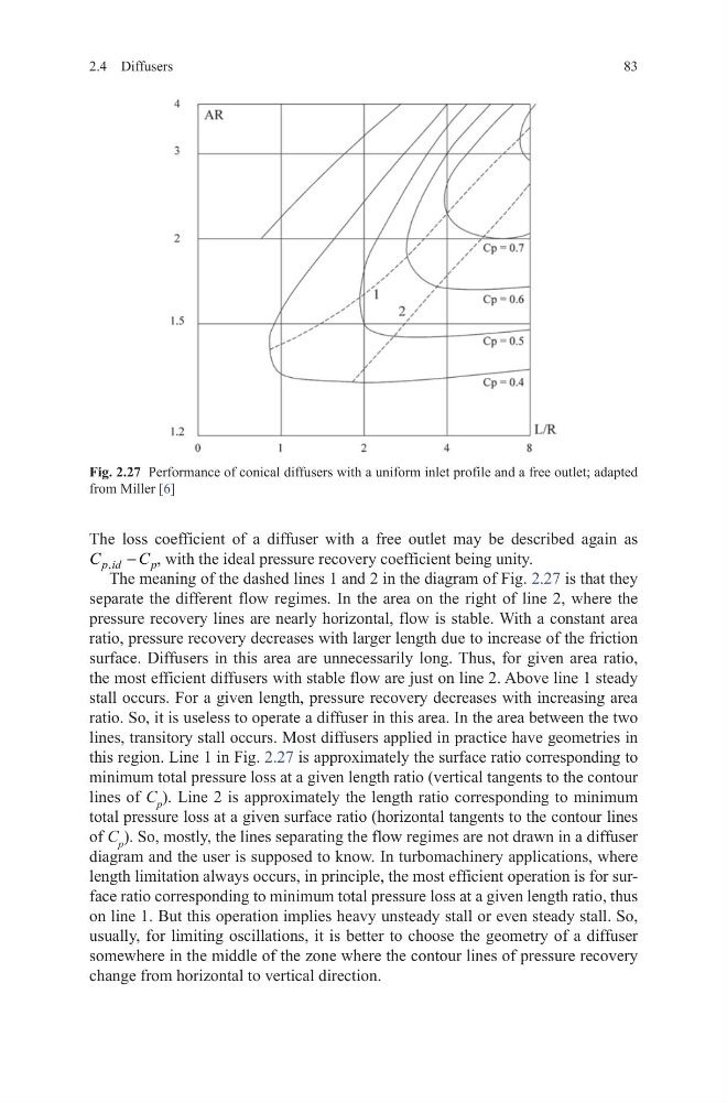
The meaning of the dashed lines 1 and 2 in the diagram of Fig. 2.27 is that they
separate the different flow regimes. In the area on the right of line 2, where the
pressure recovery lines are nearly horizontal, flow is stable. With a constant area
ratio, pressure recovery decreases with larger length due to increase of the friction
surface. Diffusers in this area are unnecessarily long. Thus, for given area ratio,
the most efficient diffusers with stable flow are just on line 2. Above line 1 steady
stall occurs. For a given length, pressure recovery decreases with increasing area
ratio. So, it is useless to operate a diffuser in this area. In the area between the two
lines, transitory stall occurs. Most diffusers applied in practice have geometries in
this region. Line 1 in Fig. 2.27 is approximately the surface ratio corresponding to
minimum total pressure loss at a given length ratio (vertical tangents to the contour
lines of C p ). Line 2 is approximately the length ratio corresponding to minimum
total pressure loss at a given surface ratio (horizontal tangents to the contour lines
of C p ). So, mostly, the lines separating the flow regimes are not drawn in a diffuser
diagram and the user is supposed to know. In turbomachinery applications, where
length limitation always occurs, in principle, the most efficient operation is for surface ratio corresponding to minimum total pressure loss at a given length ratio, thus
on line 1. But this operation implies heavy unsteady stall or even steady stall. So,
usually, for limiting oscillations, it is better to choose the geometry of a diffuser
somewhere in the middle of the zone where the contour lines of pressure recovery
change from horizontal to vertical direction.
Fig. 2.27 Performance of conical diffusers with a uniform inlet profile and a free outlet; adapted
from Miller [6]
2.4 Diffusers
The loss coefficient of a diffuser with a free outlet may be described again as
,
p id
p
C
C
− , with the ideal pressure recovery coefficient being unity.
The meaning of the dashed lines 1 and 2 in the diagram of Fig. 2.27 is that they
separate the different flow regimes. In the area on the right of line 2, where the
pressure recovery lines are nearly horizontal, flow is stable. With a constant area
ratio, pressure recovery decreases with larger length due to increase of the friction
surface. Diffusers in this area are unnecessarily long. Thus, for given area ratio,
the most efficient diffusers with stable flow are just on line 2. Above line 1 steady
stall occurs. For a given length, pressure recovery decreases with increasing area
ratio. So, it is useless to operate a diffuser in this area. In the area between the two
lines, transitory stall occurs. Most diffusers applied in practice have geometries in
this region. Line 1 in Fig. 2.27 is approximately the surface ratio corresponding to
minimum total pressure loss at a given length ratio (vertical tangents to the contour
lines of C p ). Line 2 is approximately the length ratio corresponding to minimum
total pressure loss at a given surface ratio (horizontal tangents to the contour lines
of C p ). So, mostly, the lines separating the flow regimes are not drawn in a diffuser
diagram and the user is supposed to know. In turbomachinery applications, where
length limitation always occurs, in principle, the most efficient operation is for surface ratio corresponding to minimum total pressure loss at a given length ratio, thus
on line 1. But this operation implies heavy unsteady stall or even steady stall. So,
usually, for limiting oscillations, it is better to choose the geometry of a diffuser
somewhere in the middle of the zone where the contour lines of pressure recovery
change from horizontal to vertical direction.
Fig. 2.27 Performance of conical diffusers with a uniform inlet profile and a free outlet; adapted
from Miller [6]