

82
2 Basic Components
Mounting guiding surfaces is easy with two-dimensional diffusers, but somewhat
more complex with conical diffusers.
2.4.5 Representation of Diffuser Performance
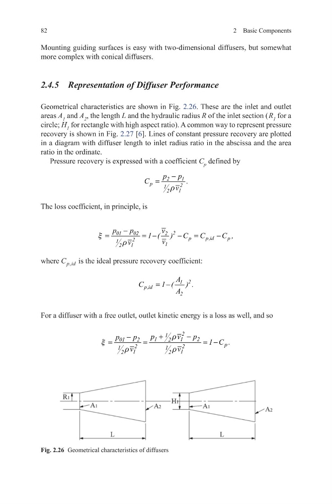
Geometrical characteristics are shown in Fig. 2.26. These are the inlet and outlet
areas A 1 and A 2 , the length L and the hydraulic radius R of the inlet section ( R 1 for a
circle; H 1 for rectangle with high aspect ratio). A common way to represent pressure
recovery is shown in Fig. 2.27 [6]. Lines of constant pressure recovery are plotted
in a diagram with diffuser length to inlet radius ratio in the abscissa and the area
ratio in the ordinate.
Pressure recovery is expressed with a coefficient C p defined by
The loss coefficient, in principle, is
where C p id
, is the ideal pressure recovery coefficient:
For a diffuser with a free outlet, outlet kinetic energy is a loss as well, and so
2
1
p
2
1
1
2
p
C
.
p
v
r
−
=
2
01
02
2
p
p ,id
p
2
1
1
1
2
p
p
v
1 ( ) C
C
C
v
v
,
x
r
−
=
= −
−
=
−
2
1
p ,id
2
A
C
1 ( A
.
)
= −
2
1
1
1
2
01
2
2
p
2
2
1
1
1
1
2
2
p
v
p
p
p
1 C .
v
v
r
x
r
r
+
−
−
=
=
= −
Fig. 2.26 Geometrical characteristics of diffusers
2 Basic Components
Mounting guiding surfaces is easy with two-dimensional diffusers, but somewhat
more complex with conical diffusers.
2.4.5 Representation of Diffuser Performance
Geometrical characteristics are shown in Fig. 2.26. These are the inlet and outlet
areas A 1 and A 2 , the length L and the hydraulic radius R of the inlet section ( R 1 for a
circle; H 1 for rectangle with high aspect ratio). A common way to represent pressure
recovery is shown in Fig. 2.27 [6]. Lines of constant pressure recovery are plotted
in a diagram with diffuser length to inlet radius ratio in the abscissa and the area
ratio in the ordinate.
Pressure recovery is expressed with a coefficient C p defined by
The loss coefficient, in principle, is
where C p id
, is the ideal pressure recovery coefficient:
For a diffuser with a free outlet, outlet kinetic energy is a loss as well, and so
2
1
p
2
1
1
2
p
C
.
p
v
r
−
=
2
01
02
2
p
p ,id
p
2
1
1
1
2
p
p
v
1 ( ) C
C
C
v
v
,
x
r
−
=
= −
−
=
−
2
1
p ,id
2
A
C
1 ( A
.
)
= −
2
1
1
1
2
01
2
2
p
2
2
1
1
1
1
2
2
p
v
p
p
p
1 C .
v
v
r
x
r
r
+
−
−
=
=
= −
Fig. 2.26 Geometrical characteristics of diffusers