

81
2.4 Diffusers
fuser. The flow structure is not highly different from that with dump diffusion.
Diffusion within a gradually widening channel so intrinsically is a process with
high losses.
2.4.3 Flow Separation
Separation occurs when the divergence of a diffuser is too strong. Pressure recovery
within a diffuser with large separation is low and the exit flow is heavily deformed,
with backflow at some places. Large-scale backflow is illustrated in Fig. 2.23 (left).
It occurs with strong divergence and is nearly steady. The flow pattern is denominated steady stall. With less strong divergence, the separation is typically time
dependent. Separation zones then build up repeatedly inside the diffuser and are
moved out by convection. This growth and removal pattern is termed transitory
stall. When diffusers function in transitory stall, large fluctuations in pressure recovery and outlet velocity distribution occur. A separation zone with strong backflow, as in Fig. 2.23 (left), causes large mixing losses downstream of the diffuser. It
might then be more advantageous to combine a diffuser with a lower opening angle
with a dump diffuser, as shown in Fig. 2.23 (right).
2.4.4 Flow Improvement
As the efficiency of a diffuser depends strongly on the uniformity of the velocity
at the inlet, efficient diffusion might be impossible if the inlet velocity varies too
much. Figure 2.24 shows, as an example, a diffuser downstream of a bend. It is then
better to postpone the diffusion in order to reduce the distortion of the profile and to
concentrate the divergence of the diffuser on the higher energy side.
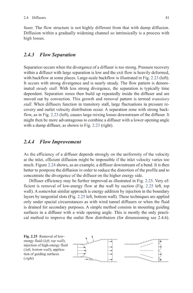
Diffuser efficiency may be further improved as illustrated in Fig. 2.25. Very efficient is removal of low-energy flow at the wall by suction (Fig. 2.25 left, top
wall). A somewhat similar approach is energy addition by injection in the boundary
layers by tangential slots (Fig. 2.25 left, bottom wall). These techniques are applied
only under special circumstances as with wind tunnel diffusers or when the fluid
is drained for secondary purposes. A simple method consists in mounting guiding
surfaces in a diffuser with a wide opening angle. This is mostly the only practical method to improve the outlet flow distribution (for dimensioning see 2.4.6).
Fig. 2.25 Removal of lowenergy fluid ( left; top wall);
injection of high-energy fluid
( left; bottom wall); application of guiding surfaces
( right)
2.4 Diffusers
fuser. The flow structure is not highly different from that with dump diffusion.
Diffusion within a gradually widening channel so intrinsically is a process with
high losses.
2.4.3 Flow Separation
Separation occurs when the divergence of a diffuser is too strong. Pressure recovery
within a diffuser with large separation is low and the exit flow is heavily deformed,
with backflow at some places. Large-scale backflow is illustrated in Fig. 2.23 (left).
It occurs with strong divergence and is nearly steady. The flow pattern is denominated steady stall. With less strong divergence, the separation is typically time
dependent. Separation zones then build up repeatedly inside the diffuser and are
moved out by convection. This growth and removal pattern is termed transitory
stall. When diffusers function in transitory stall, large fluctuations in pressure recovery and outlet velocity distribution occur. A separation zone with strong backflow, as in Fig. 2.23 (left), causes large mixing losses downstream of the diffuser. It
might then be more advantageous to combine a diffuser with a lower opening angle
with a dump diffuser, as shown in Fig. 2.23 (right).
2.4.4 Flow Improvement
As the efficiency of a diffuser depends strongly on the uniformity of the velocity
at the inlet, efficient diffusion might be impossible if the inlet velocity varies too
much. Figure 2.24 shows, as an example, a diffuser downstream of a bend. It is then
better to postpone the diffusion in order to reduce the distortion of the profile and to
concentrate the divergence of the diffuser on the higher energy side.
Diffuser efficiency may be further improved as illustrated in Fig. 2.25. Very efficient is removal of low-energy flow at the wall by suction (Fig. 2.25 left, top
wall). A somewhat similar approach is energy addition by injection in the boundary
layers by tangential slots (Fig. 2.25 left, bottom wall). These techniques are applied
only under special circumstances as with wind tunnel diffusers or when the fluid
is drained for secondary purposes. A simple method consists in mounting guiding
surfaces in a diffuser with a wide opening angle. This is mostly the only practical method to improve the outlet flow distribution (for dimensioning see 2.4.6).
Fig. 2.25 Removal of lowenergy fluid ( left; top wall);
injection of high-energy fluid
( left; bottom wall); application of guiding surfaces
( right)