

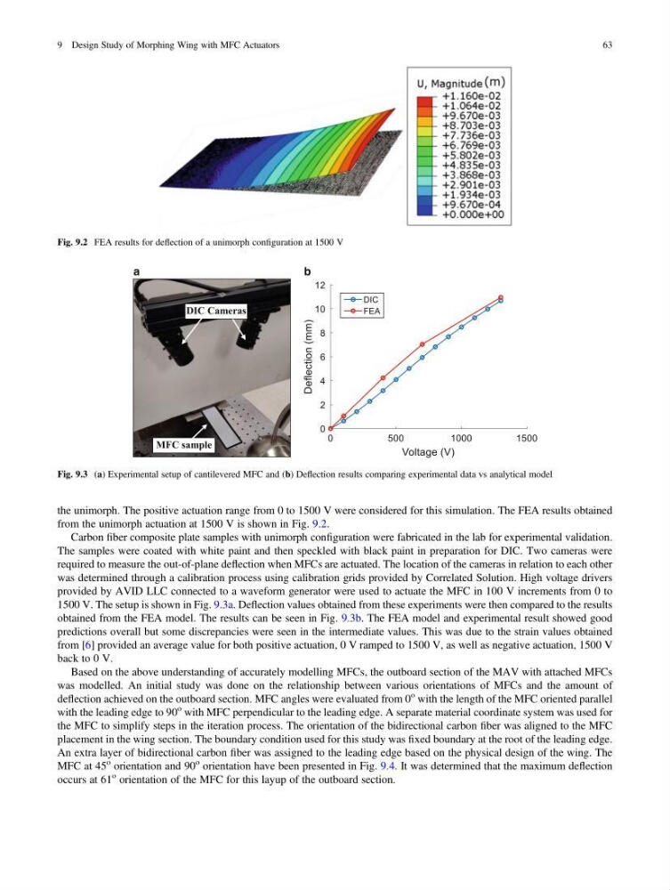
the unimorph. The positive actuation range from 0 to 1500 V were considered for this simulation. The FEA results obtained
from the unimorph actuation at 1500 V is shown in Fig. 9.2.
Carbon fiber composite plate samples with unimorph configuration were fabricated in the lab for experimental validation.
The samples were coated with white paint and then speckled with black paint in preparation for DIC. Two cameras were
required to measure the out-of-plane deflection when MFCs are actuated. The location of the cameras in relation to each other
was determined through a calibration process using calibration grids provided by Correlated Solution. High voltage drivers
provided by AVID LLC connected to a waveform generator were used to actuate the MFC in 100 V increments from 0 to
1500 V. The setup is shown in Fig. 9.3a. Deflection values obtained from these experiments were then compared to the results
obtained from the FEA model. The results can be seen in Fig. 9.3b. The FEA model and experimental result showed good
predictions overall but some discrepancies were seen in the intermediate values. This was due to the strain values obtained
from [6] provided an average value for both positive actuation, 0 V ramped to 1500 V, as well as negative actuation, 1500 V
back to 0 V.
Based on the above understanding of accurately modelling MFCs, the outboard section of the MAV with attached MFCs
was modelled. An initial study was done on the relationship between various orientations of MFCs and the amount of
deflection achieved on the outboard section. MFC angles were evaluated from 0
o with the length of the MFC oriented parallel
with the leading edge to 90
o with MFC perpendicular to the leading edge. A separate material coordinate system was used for
the MFC to simplify steps in the iteration process. The orientation of the bidirectional carbon fiber was aligned to the MFC
placement in the wing section. The boundary condition used for this study was fixed boundary at the root of the leading edge.
An extra layer of bidirectional carbon fiber was assigned to the leading edge based on the physical design of the wing. The
MFC at 45
o orientation and 90
o orientation have been presented in Fig. 9.4. It was determined that the maximum deflection
occurs at 61
o orientation of the MFC for this layup of the outboard section.
Fig. 9.2 FEA results for deflection of a unimorph configuration at 1500 V
DIC Cameras
a
b
MFC sample
Fig. 9.3 (a) Experimental setup of cantilevered MFC and (b) Deflection results comparing experimental data vs analytical model
9 Design Study of Morphing Wing with MFC Actuators
63
from the unimorph actuation at 1500 V is shown in Fig. 9.2.
Carbon fiber composite plate samples with unimorph configuration were fabricated in the lab for experimental validation.
The samples were coated with white paint and then speckled with black paint in preparation for DIC. Two cameras were
required to measure the out-of-plane deflection when MFCs are actuated. The location of the cameras in relation to each other
was determined through a calibration process using calibration grids provided by Correlated Solution. High voltage drivers
provided by AVID LLC connected to a waveform generator were used to actuate the MFC in 100 V increments from 0 to
1500 V. The setup is shown in Fig. 9.3a. Deflection values obtained from these experiments were then compared to the results
obtained from the FEA model. The results can be seen in Fig. 9.3b. The FEA model and experimental result showed good
predictions overall but some discrepancies were seen in the intermediate values. This was due to the strain values obtained
from [6] provided an average value for both positive actuation, 0 V ramped to 1500 V, as well as negative actuation, 1500 V
back to 0 V.
Based on the above understanding of accurately modelling MFCs, the outboard section of the MAV with attached MFCs
was modelled. An initial study was done on the relationship between various orientations of MFCs and the amount of
deflection achieved on the outboard section. MFC angles were evaluated from 0
o with the length of the MFC oriented parallel
with the leading edge to 90
o with MFC perpendicular to the leading edge. A separate material coordinate system was used for
the MFC to simplify steps in the iteration process. The orientation of the bidirectional carbon fiber was aligned to the MFC
placement in the wing section. The boundary condition used for this study was fixed boundary at the root of the leading edge.
An extra layer of bidirectional carbon fiber was assigned to the leading edge based on the physical design of the wing. The
MFC at 45
o orientation and 90
o orientation have been presented in Fig. 9.4. It was determined that the maximum deflection
occurs at 61
o orientation of the MFC for this layup of the outboard section.
Fig. 9.2 FEA results for deflection of a unimorph configuration at 1500 V
DIC Cameras
a
b
MFC sample
Fig. 9.3 (a) Experimental setup of cantilevered MFC and (b) Deflection results comparing experimental data vs analytical model
9 Design Study of Morphing Wing with MFC Actuators
63