

strength when oriented at 45
o angle. Several samples were fabricated for tensile testing from each type of composite at various
orientation to determine the material properties to be inputted into the finite element solver. Digital image correlation (DIC)
was used for measuring the strain in the samples. DIC is a non-contact full-field measurement tool used to measure
displacements and strains [3]. It uses cameras to track and record the movement of randomly applied patterns known as
speckle patterns. A commercially available systems developed by Correlated Solutions was used for this process. The camera
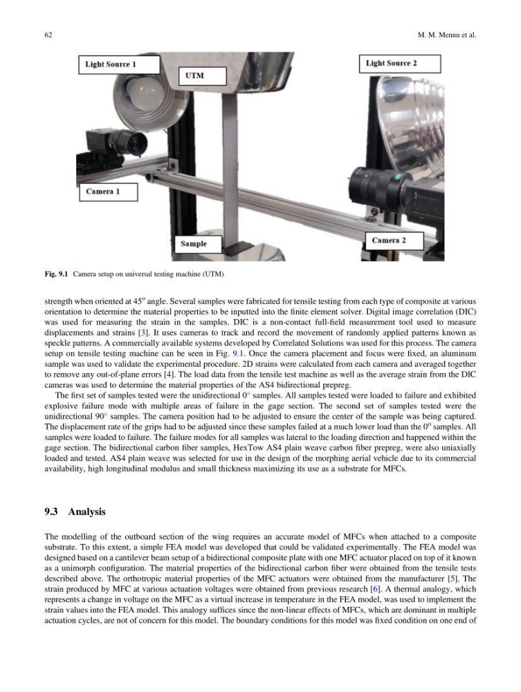
setup on tensile testing machine can be seen in Fig. 9.1. Once the camera placement and focus were fixed, an aluminum
sample was used to validate the experimental procedure. 2D strains were calculated from each camera and averaged together
to remove any out-of-plane errors [4]. The load data from the tensile test machine as well as the average strain from the DIC
cameras was used to determine the material properties of the AS4 bidirectional prepreg.
The first set of samples tested were the unidirectional 0
samples. All samples tested were loaded to failure and exhibited
explosive failure mode with multiple areas of failure in the gage section. The second set of samples tested were the
unidirectional 90
samples. The camera position had to be adjusted to ensure the center of the sample was being captured.
The displacement rate of the grips had to be adjusted since these samples failed at a much lower load than the 0
o samples. All
samples were loaded to failure. The failure modes for all samples was lateral to the loading direction and happened within the
gage section. The bidirectional carbon fiber samples, HexTow AS4 plain weave carbon fiber prepreg, were also uniaxially
loaded and tested. AS4 plain weave was selected for use in the design of the morphing aerial vehicle due to its commercial
availability, high longitudinal modulus and small thickness maximizing its use as a substrate for MFCs.
9.3 Analysis
The modelling of the outboard section of the wing requires an accurate model of MFCs when attached to a composite
substrate. To this extent, a simple FEA model was developed that could be validated experimentally. The FEA model was
designed based on a cantilever beam setup of a bidirectional composite plate with one MFC actuator placed on top of it known
as a unimorph configuration. The material properties of the bidirectional carbon fiber were obtained from the tensile tests
described above. The orthotropic material properties of the MFC actuators were obtained from the manufacturer [5]. The
strain produced by MFC at various actuation voltages were obtained from previous research [6]. A thermal analogy, which
represents a change in voltage on the MFC as a virtual increase in temperature in the FEA model, was used to implement the
strain values into the FEA model. This analogy suffices since the non-linear effects of MFCs, which are dominant in multiple
actuation cycles, are not of concern for this model. The boundary conditions for this model was fixed condition on one end of
Fig. 9.1 Camera setup on universal testing machine (UTM)
62
M. M. Mennu et al.
o angle. Several samples were fabricated for tensile testing from each type of composite at various
orientation to determine the material properties to be inputted into the finite element solver. Digital image correlation (DIC)
was used for measuring the strain in the samples. DIC is a non-contact full-field measurement tool used to measure
displacements and strains [3]. It uses cameras to track and record the movement of randomly applied patterns known as
speckle patterns. A commercially available systems developed by Correlated Solutions was used for this process. The camera
setup on tensile testing machine can be seen in Fig. 9.1. Once the camera placement and focus were fixed, an aluminum
sample was used to validate the experimental procedure. 2D strains were calculated from each camera and averaged together
to remove any out-of-plane errors [4]. The load data from the tensile test machine as well as the average strain from the DIC
cameras was used to determine the material properties of the AS4 bidirectional prepreg.
The first set of samples tested were the unidirectional 0
samples. All samples tested were loaded to failure and exhibited
explosive failure mode with multiple areas of failure in the gage section. The second set of samples tested were the
unidirectional 90
samples. The camera position had to be adjusted to ensure the center of the sample was being captured.
The displacement rate of the grips had to be adjusted since these samples failed at a much lower load than the 0
o samples. All
samples were loaded to failure. The failure modes for all samples was lateral to the loading direction and happened within the
gage section. The bidirectional carbon fiber samples, HexTow AS4 plain weave carbon fiber prepreg, were also uniaxially
loaded and tested. AS4 plain weave was selected for use in the design of the morphing aerial vehicle due to its commercial
availability, high longitudinal modulus and small thickness maximizing its use as a substrate for MFCs.
9.3 Analysis
The modelling of the outboard section of the wing requires an accurate model of MFCs when attached to a composite
substrate. To this extent, a simple FEA model was developed that could be validated experimentally. The FEA model was
designed based on a cantilever beam setup of a bidirectional composite plate with one MFC actuator placed on top of it known
as a unimorph configuration. The material properties of the bidirectional carbon fiber were obtained from the tensile tests
described above. The orthotropic material properties of the MFC actuators were obtained from the manufacturer [5]. The
strain produced by MFC at various actuation voltages were obtained from previous research [6]. A thermal analogy, which
represents a change in voltage on the MFC as a virtual increase in temperature in the FEA model, was used to implement the
strain values into the FEA model. This analogy suffices since the non-linear effects of MFCs, which are dominant in multiple
actuation cycles, are not of concern for this model. The boundary conditions for this model was fixed condition on one end of
Fig. 9.1 Camera setup on universal testing machine (UTM)
62
M. M. Mennu et al.