

9.4 Conclusion
Several considerations have to be taken when attempting to accurately model a wing structure for a MAV incorporating MFC
actuators. The material properties for the composite structure have been identified experimentally In addition, a simple model
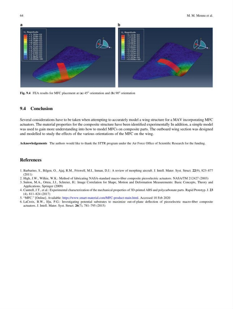
was used to gain more understanding into how to model MFCs on composite parts. The outboard wing section was designed
and modelled to study the effects of the various orientations of the MFC on the wing.
Acknowledgements The authors would like to thank the STTR program under the Air Force Office of Scientific Research for the funding.
References
1. Barbarino, S., Bilgen, O., Ajaj, R.M., Friswell, M.I., Inman, D.J.: A review of morphing aircraft. J. Intell. Mater. Syst. Struct. 22(9), 823–877
(2011)
2. High, J.W., Wilkie, W.K.: Method of fabricating NASA-standard macro-fiber composite piezoelectric actuators. NASA/TM 212427 (2003)
3. Sutton, M.A., Orteu, J.J., Schreier, H.: Image Correlation for Shape, Motion and Deformation Measurements: Basic Concepts, Theory and
Applications. Springer (2009)
4. Cantrell, J.T., et al.: Experimental characterization of the mechanical properties of 3D-printed ABS and polycarbonate parts. Rapid Prototyp. J. 23
(4), 811–824 (2017)
5. “MFC.” [Online]. Available: https://www.smart-material.com/MFC-product-main.html. Accessed 18 Feb 2020
6. LaCroix, B.W., Ifju, P.G.: Investigating potential substrates to maximize out-of-plane deflection of piezoelectric macro-fiber composite
actuators. J. Intell. Mater. Syst. Struct. 26(7), 781–795 (2015)
Fig. 9.4 FEA results for MFC placement at (a) 45
o orientation and (b) 90
o orientation
64
M. M. Mennu et al.
Several considerations have to be taken when attempting to accurately model a wing structure for a MAV incorporating MFC
actuators. The material properties for the composite structure have been identified experimentally In addition, a simple model
was used to gain more understanding into how to model MFCs on composite parts. The outboard wing section was designed
and modelled to study the effects of the various orientations of the MFC on the wing.
Acknowledgements The authors would like to thank the STTR program under the Air Force Office of Scientific Research for the funding.
References
1. Barbarino, S., Bilgen, O., Ajaj, R.M., Friswell, M.I., Inman, D.J.: A review of morphing aircraft. J. Intell. Mater. Syst. Struct. 22(9), 823–877
(2011)
2. High, J.W., Wilkie, W.K.: Method of fabricating NASA-standard macro-fiber composite piezoelectric actuators. NASA/TM 212427 (2003)
3. Sutton, M.A., Orteu, J.J., Schreier, H.: Image Correlation for Shape, Motion and Deformation Measurements: Basic Concepts, Theory and
Applications. Springer (2009)
4. Cantrell, J.T., et al.: Experimental characterization of the mechanical properties of 3D-printed ABS and polycarbonate parts. Rapid Prototyp. J. 23
(4), 811–824 (2017)
5. “MFC.” [Online]. Available: https://www.smart-material.com/MFC-product-main.html. Accessed 18 Feb 2020
6. LaCroix, B.W., Ifju, P.G.: Investigating potential substrates to maximize out-of-plane deflection of piezoelectric macro-fiber composite
actuators. J. Intell. Mater. Syst. Struct. 26(7), 781–795 (2015)
Fig. 9.4 FEA results for MFC placement at (a) 45
o orientation and (b) 90
o orientation
64
M. M. Mennu et al.