

J t
ð Þ ¼ A t
ð Þ= 1 À ν
ð
ÞP 0 tan θ
ð8:4Þ
In Eq. (8.3), A(t) is the contact area, P 0 constant applied load, θ is the effective cone angle which is 70.3
for a Berkovich
indenter and the Poisson’s ratio ν is assumed to be 0.3. This approach takes into account how the contact area under the
Berkovich tip alters while displacement into the surface changes.
The strain versus time behaviour during creep is characterized by a high strain rate in the primary stage of creep and then in
the secondary, steady state stage of creep, the strain rate is given in Eq. (8.5) can be written as
_
ε ¼ Kσ
n
ð8:5Þ
where K is a constant and n is the stress exponent. The strain rate is calculated in the software and in turn n is obtained from the
log-log plot of strain rate versus stress in the secondary stage of creep.
The materials under consideration are heterogeneous in nature and the fact that the nanoindentation test is carried out over a
small area/volume, a large scatter in the data is observed and to overcome this sampling number was taken as large as possible.
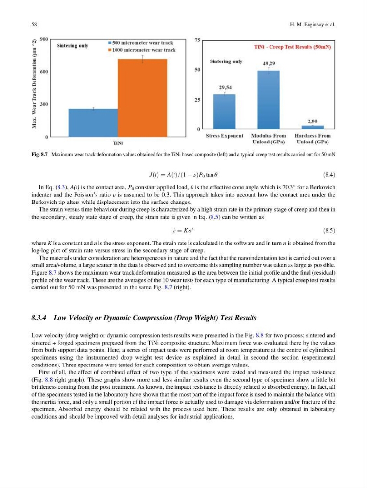
Figure 8.7 shows the maximum wear track deformation measured as the area between the initial profile and the final (residual)
profile of the wear track. These are the averages of the 10 wear tests for each type of manufacturing. A typical creep test results
carried out for 50 mN was presented in the same Fig. 8.7 (right).
8.3.4 Low Velocity or Dynamic Compression (Drop Weight) Test Results
Low velocity (drop weight) or dynamic compression tests results were presented in the Fig. 8.8 for two process; sintered and
sintered + forged specimens prepared from the TiNi composite structure. Maximum force was evaluated there by the values
from both support data points. Here, a series of impact tests were performed at room temperature at the centre of cylindrical
specimens using the instrumented drop weight test device as explained in detail in second the section (experimental
conditions). Three specimens were tested for each composition to obtain average values.
First of all, the effect of combined effect of two type of the specimens were tested and measured the impact resistance
(Fig. 8.8 right graph). These graphs show more and less similar results even the second type of specimen show a little bit
brittleness coming from the post treatment. As known, the impact resistance is directly related to absorbed energy. In fact, all
of the specimens tested in the laboratory have shown that the most part of the impact force is used to maintain the balance with
the inertia force, and only a small portion of the impact force is actually used to damage via deformation and/or fracture of the
specimen. Absorbed energy should be related with the process used here. These results are only obtained in laboratory
conditions and should be improved with detail analyses for industrial applications.
Fig. 8.7 Maximum wear track deformation values obtained for the TiNi based composite (left) and a typical creep test results carried out for 50 mN
58
H. M. Enginsoy et al.
ð Þ ¼ A t
ð Þ= 1 À ν
ð
ÞP 0 tan θ
ð8:4Þ
In Eq. (8.3), A(t) is the contact area, P 0 constant applied load, θ is the effective cone angle which is 70.3
for a Berkovich
indenter and the Poisson’s ratio ν is assumed to be 0.3. This approach takes into account how the contact area under the
Berkovich tip alters while displacement into the surface changes.
The strain versus time behaviour during creep is characterized by a high strain rate in the primary stage of creep and then in
the secondary, steady state stage of creep, the strain rate is given in Eq. (8.5) can be written as
_
ε ¼ Kσ
n
ð8:5Þ
where K is a constant and n is the stress exponent. The strain rate is calculated in the software and in turn n is obtained from the
log-log plot of strain rate versus stress in the secondary stage of creep.
The materials under consideration are heterogeneous in nature and the fact that the nanoindentation test is carried out over a
small area/volume, a large scatter in the data is observed and to overcome this sampling number was taken as large as possible.
Figure 8.7 shows the maximum wear track deformation measured as the area between the initial profile and the final (residual)
profile of the wear track. These are the averages of the 10 wear tests for each type of manufacturing. A typical creep test results
carried out for 50 mN was presented in the same Fig. 8.7 (right).
8.3.4 Low Velocity or Dynamic Compression (Drop Weight) Test Results
Low velocity (drop weight) or dynamic compression tests results were presented in the Fig. 8.8 for two process; sintered and
sintered + forged specimens prepared from the TiNi composite structure. Maximum force was evaluated there by the values
from both support data points. Here, a series of impact tests were performed at room temperature at the centre of cylindrical
specimens using the instrumented drop weight test device as explained in detail in second the section (experimental
conditions). Three specimens were tested for each composition to obtain average values.
First of all, the effect of combined effect of two type of the specimens were tested and measured the impact resistance
(Fig. 8.8 right graph). These graphs show more and less similar results even the second type of specimen show a little bit
brittleness coming from the post treatment. As known, the impact resistance is directly related to absorbed energy. In fact, all
of the specimens tested in the laboratory have shown that the most part of the impact force is used to maintain the balance with
the inertia force, and only a small portion of the impact force is actually used to damage via deformation and/or fracture of the
specimen. Absorbed energy should be related with the process used here. These results are only obtained in laboratory
conditions and should be improved with detail analyses for industrial applications.
Fig. 8.7 Maximum wear track deformation values obtained for the TiNi based composite (left) and a typical creep test results carried out for 50 mN
58
H. M. Enginsoy et al.