

In the Eq. (8.2), bending deformation was considered on the outer surface of the test piece
ε f ¼
6Dd
L
2
ð8:2Þ
Finally, 5 mm discreet rigid cylinder tool was accepted for the general contact in order to simulate the punch that was used
on the experimental setup.
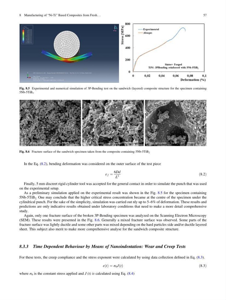
As a preliminary simulation applied on the experimental result was shown in the Fig. 8.5 for the specimen containing
5Nb-5TiB 2. One may conclude that the higher critical stress concentration became at the centre of the specimen under the
cylindrical punch. For the sake of the simplicity, simulation was carried out nly up to 5–6% of deformation. These results and
predictions are only indicative results obtained under laboratory conditions that need to make a more detail comprehensive
study.
Again, only one fracture surface of the broken 3P-Bending specimen was analyzed on the Scanning Electron Microscopy
(SEM). These results were presented in the Fig. 8.6. Generally a mixed fracture surface was observed. Some parts of the
fracture surface was lightly ductile and some other parts was mixed depending on the hard particles side and/or ductile layered
sheet. This subject also merit to make more comprehensive analyse for the sandwich composite structure.
8.3.3 Time Dependent Behaviour by Means of Nanoindentation: Wear and Creep Tests
For these tests, the creep compliance and the stress exponent were calculated by using data collection defined in Eq. (8.3).
ε t
ð Þ ¼ σ 0 J t
ð Þ
ð8:3Þ
where σ 0 is the constant stress applied and J (t) is calculated using Eq. (8.4)
Fig. 8.5 Experimental and numerical simulation of 3P-Bending test on the sandwich (layered) composite structure for the specimen containing
5Nb-5TiB 2
Fig. 8.6 Fracture surface of the sandwich specimen taken from the composite containing 5Nb-5TiB 2
8 Manufacturing of “Ni-Ti” Based Composites from Fresh. . .
57
ε f ¼
6Dd
L
2
ð8:2Þ
Finally, 5 mm discreet rigid cylinder tool was accepted for the general contact in order to simulate the punch that was used
on the experimental setup.
As a preliminary simulation applied on the experimental result was shown in the Fig. 8.5 for the specimen containing
5Nb-5TiB 2. One may conclude that the higher critical stress concentration became at the centre of the specimen under the
cylindrical punch. For the sake of the simplicity, simulation was carried out nly up to 5–6% of deformation. These results and
predictions are only indicative results obtained under laboratory conditions that need to make a more detail comprehensive
study.
Again, only one fracture surface of the broken 3P-Bending specimen was analyzed on the Scanning Electron Microscopy
(SEM). These results were presented in the Fig. 8.6. Generally a mixed fracture surface was observed. Some parts of the
fracture surface was lightly ductile and some other parts was mixed depending on the hard particles side and/or ductile layered
sheet. This subject also merit to make more comprehensive analyse for the sandwich composite structure.
8.3.3 Time Dependent Behaviour by Means of Nanoindentation: Wear and Creep Tests
For these tests, the creep compliance and the stress exponent were calculated by using data collection defined in Eq. (8.3).
ε t
ð Þ ¼ σ 0 J t
ð Þ
ð8:3Þ
where σ 0 is the constant stress applied and J (t) is calculated using Eq. (8.4)
Fig. 8.5 Experimental and numerical simulation of 3P-Bending test on the sandwich (layered) composite structure for the specimen containing
5Nb-5TiB 2
Fig. 8.6 Fracture surface of the sandwich specimen taken from the composite containing 5Nb-5TiB 2
8 Manufacturing of “Ni-Ti” Based Composites from Fresh. . .
57