

3.3 Dynamic Spalling Test
59
where u, t and x are the particle displacement, time and the longitudinal coordinate.
c is the elastic wave velocity of the specimen. By integrating Eq. (3.1), it derives
u(x, t) = f (x − ct) + g(x + ct)
(3.2)
where f (x − ct) and g(x + ct) represent the stress waves propagating in the positive
and negative x-axis direction, respectively. Based on Eq. (3.2), the strain of specimen
ε(x,t) and the velocity of particle v(x,t) can be obtained directly by the following
expressions
ε(x, t) = ∂u(x, t)/∂ x = f
x (x − ct) + g
x (x + ct)
(3.3)
v(x, t) = ∂u(x, t)/∂t = −c f
t (x − ct) + cg
t (x + ct)
(3.4)
where the subscript x and t are the derivation of coordinate and time. If linear elastic
behavior is assumed, the stress can be calculated as follows:
σ (x, t) = Eε(x, t) = E
f
x (x − ct) + g
x (x + ct)
(3.5)
By assuming an elastic compressive wave travelling along the positive x-axis
direction of a semi-infinite bar, the function f (x − ct) is the compressive wave and
the function g(x + ct) is zero. When this wave reaches the free end of the bar, the
boundary condition is that the stress at the free end should be zero: σ (x, t) = 0. This
means that the following relationship is satisfied at the boundary.
f
x (x − ct) = −g
x (x + ct)
(3.6)
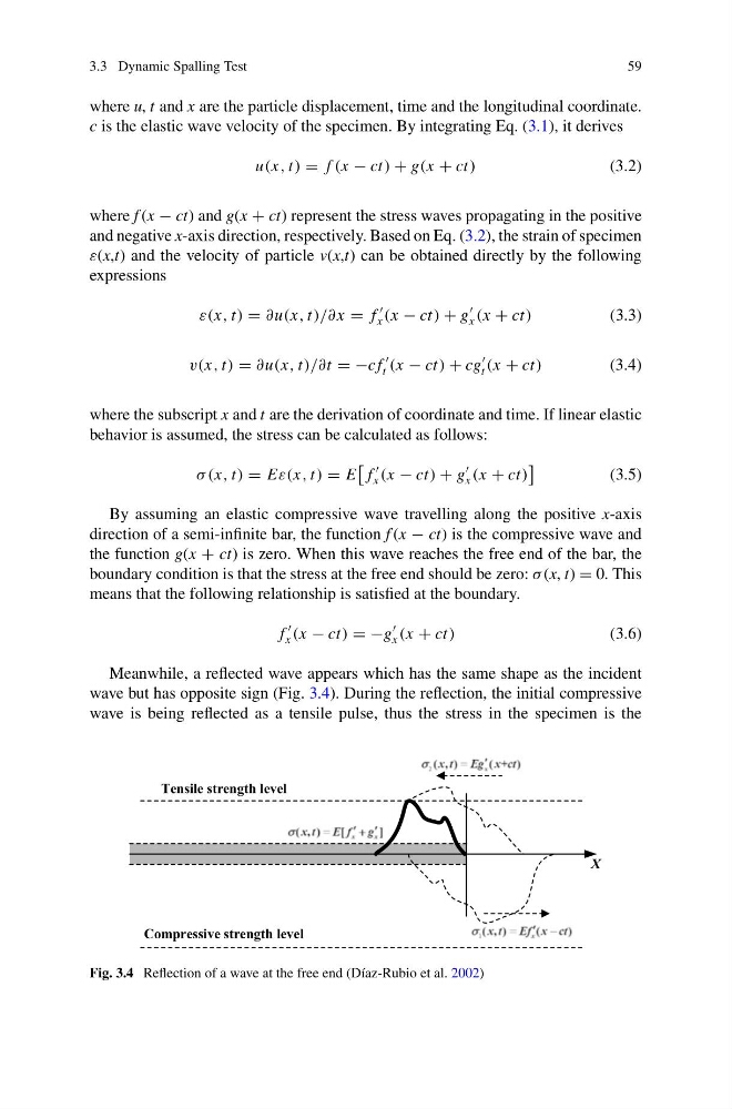
Meanwhile, a reflected wave appears which has the same shape as the incident
wave but has opposite sign (Fig. 3.4). During the reflection, the initial compressive
wave is being reflected as a tensile pulse, thus the stress in the specimen is the
X
Tensile strength level
Compressive strength level
Fig. 3.4 Reflection of a wave at the free end (Díaz-Rubio et al. 2002)
59
where u, t and x are the particle displacement, time and the longitudinal coordinate.
c is the elastic wave velocity of the specimen. By integrating Eq. (3.1), it derives
u(x, t) = f (x − ct) + g(x + ct)
(3.2)
where f (x − ct) and g(x + ct) represent the stress waves propagating in the positive
and negative x-axis direction, respectively. Based on Eq. (3.2), the strain of specimen
ε(x,t) and the velocity of particle v(x,t) can be obtained directly by the following
expressions
ε(x, t) = ∂u(x, t)/∂ x = f
x (x − ct) + g
x (x + ct)
(3.3)
v(x, t) = ∂u(x, t)/∂t = −c f
t (x − ct) + cg
t (x + ct)
(3.4)
where the subscript x and t are the derivation of coordinate and time. If linear elastic
behavior is assumed, the stress can be calculated as follows:
σ (x, t) = Eε(x, t) = E
f
x (x − ct) + g
x (x + ct)
(3.5)
By assuming an elastic compressive wave travelling along the positive x-axis
direction of a semi-infinite bar, the function f (x − ct) is the compressive wave and
the function g(x + ct) is zero. When this wave reaches the free end of the bar, the
boundary condition is that the stress at the free end should be zero: σ (x, t) = 0. This
means that the following relationship is satisfied at the boundary.
f
x (x − ct) = −g
x (x + ct)
(3.6)
Meanwhile, a reflected wave appears which has the same shape as the incident
wave but has opposite sign (Fig. 3.4). During the reflection, the initial compressive
wave is being reflected as a tensile pulse, thus the stress in the specimen is the
X
Tensile strength level
Compressive strength level
Fig. 3.4 Reflection of a wave at the free end (Díaz-Rubio et al. 2002)