

58
3 Dynamic Tensile Mechanical Properties of UHPCC
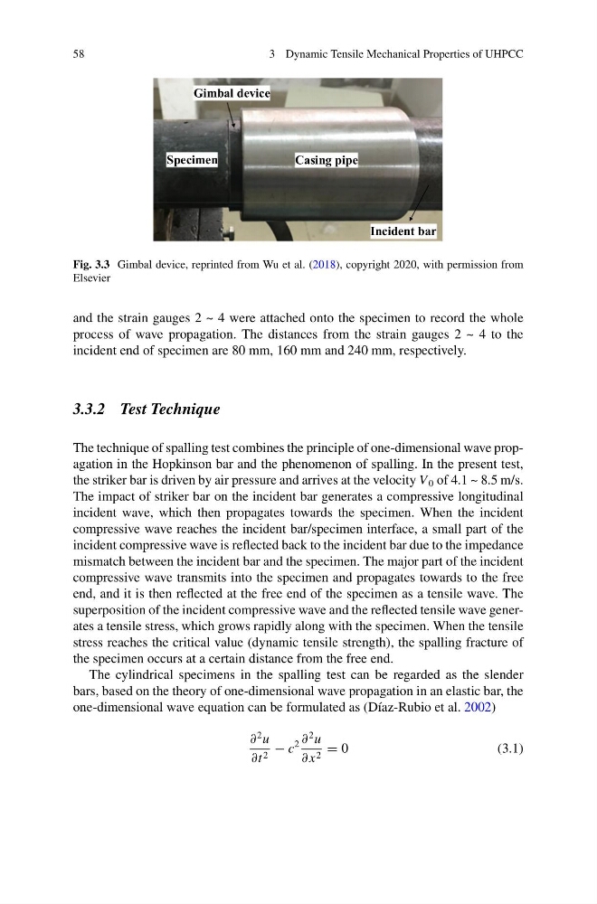
Gimbal device
Specimen
Incident bar
Casing pipe
Fig. 3.3 Gimbal device, reprinted from Wu et al. (2018), copyright 2020, with permission from
Elsevier
and the strain gauges 2 ~ 4 were attached onto the specimen to record the whole
process of wave propagation. The distances from the strain gauges 2 ~ 4 to the
incident end of specimen are 80 mm, 160 mm and 240 mm, respectively.
3.3.2 Test Technique
The technique of spalling test combines the principle of one-dimensional wave propagation in the Hopkinson bar and the phenomenon of spalling. In the present test,
the striker bar is driven by air pressure and arrives at the velocity V 0 of 4.1 ~ 8.5 m/s.
The impact of striker bar on the incident bar generates a compressive longitudinal
incident wave, which then propagates towards the specimen. When the incident
compressive wave reaches the incident bar/specimen interface, a small part of the
incident compressive wave is reflected back to the incident bar due to the impedance
mismatch between the incident bar and the specimen. The major part of the incident
compressive wave transmits into the specimen and propagates towards to the free
end, and it is then reflected at the free end of the specimen as a tensile wave. The
superposition of the incident compressive wave and the reflected tensile wave generates a tensile stress, which grows rapidly along with the specimen. When the tensile
stress reaches the critical value (dynamic tensile strength), the spalling fracture of
the specimen occurs at a certain distance from the free end.
The cylindrical specimens in the spalling test can be regarded as the slender
bars, based on the theory of one-dimensional wave propagation in an elastic bar, the
one-dimensional wave equation can be formulated as (Díaz-Rubio et al. 2002)
∂
2 u
∂t 2 − c
2 ∂
2 u
∂ x 2 = 0
(3.1)
3 Dynamic Tensile Mechanical Properties of UHPCC
Gimbal device
Specimen
Incident bar
Casing pipe
Fig. 3.3 Gimbal device, reprinted from Wu et al. (2018), copyright 2020, with permission from
Elsevier
and the strain gauges 2 ~ 4 were attached onto the specimen to record the whole
process of wave propagation. The distances from the strain gauges 2 ~ 4 to the
incident end of specimen are 80 mm, 160 mm and 240 mm, respectively.
3.3.2 Test Technique
The technique of spalling test combines the principle of one-dimensional wave propagation in the Hopkinson bar and the phenomenon of spalling. In the present test,
the striker bar is driven by air pressure and arrives at the velocity V 0 of 4.1 ~ 8.5 m/s.
The impact of striker bar on the incident bar generates a compressive longitudinal
incident wave, which then propagates towards the specimen. When the incident
compressive wave reaches the incident bar/specimen interface, a small part of the
incident compressive wave is reflected back to the incident bar due to the impedance
mismatch between the incident bar and the specimen. The major part of the incident
compressive wave transmits into the specimen and propagates towards to the free
end, and it is then reflected at the free end of the specimen as a tensile wave. The
superposition of the incident compressive wave and the reflected tensile wave generates a tensile stress, which grows rapidly along with the specimen. When the tensile
stress reaches the critical value (dynamic tensile strength), the spalling fracture of
the specimen occurs at a certain distance from the free end.
The cylindrical specimens in the spalling test can be regarded as the slender
bars, based on the theory of one-dimensional wave propagation in an elastic bar, the
one-dimensional wave equation can be formulated as (Díaz-Rubio et al. 2002)
∂
2 u
∂t 2 − c
2 ∂
2 u
∂ x 2 = 0
(3.1)