

3.2 Specimen Preparation
57
Table 3.1 Quasi-static cubic compressive strengths of UHPCC
Test no.
N-0
S-1
S-2
H-1
H-2
Quasi-static cubic compressive strength (MPa)
109
136
152
119
138
fiber orientation and distribution. In order to make the specimen-bar contact as perfect
as possible, the end surfaces of all specimens were carefully polished, which were
flatted to less than 0.1 mm, and the roughness on the surfaces was less than 0.05 mm.
Besides, 15 cubic control specimens for each batch with the size of 100 × 100 ×
100 mm were cast and tested, and the average quasi-static compressive strengths are
listed in Table 3.1. In which the capitals “N”, “S” and “H” represent no mixing fiber,
micro-straight steel fiber and hooked steel fiber, and the numbers “0”, “1” and “2”
denote that the volume fractions of steel fibers are 0%, 1.0% and 2.0%, respectively.
The similar designation way is adopted in the following spalling test.
3.3 Dynamic Spalling Test
3.3.1 Test Device
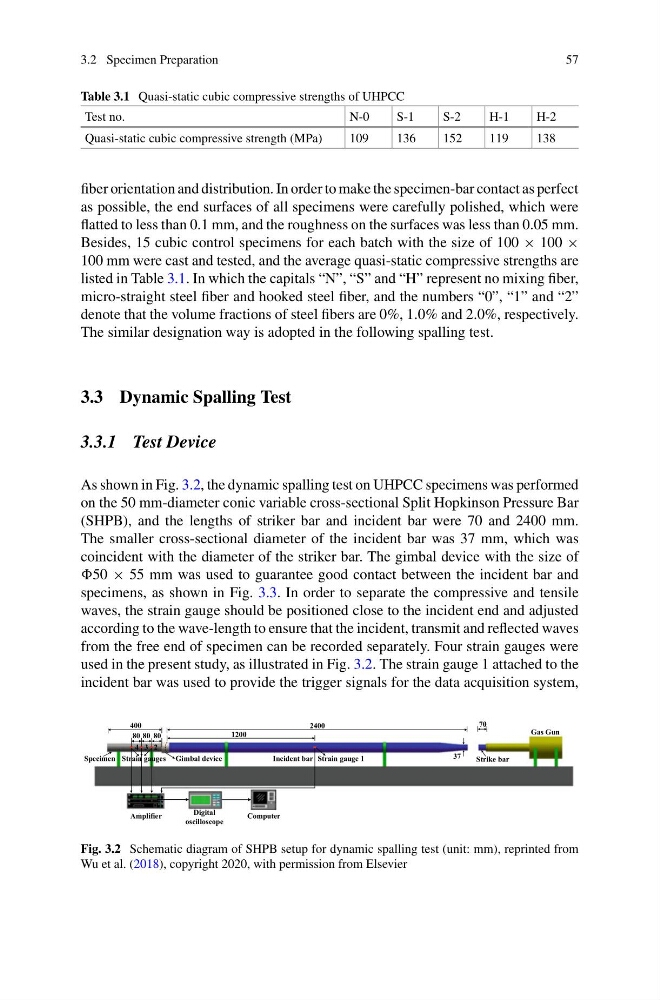
As shown in Fig. 3.2, the dynamic spalling test on UHPCC specimens was performed
on the 50 mm-diameter conic variable cross-sectional Split Hopkinson Pressure Bar
(SHPB), and the lengths of striker bar and incident bar were 70 and 2400 mm.
The smaller cross-sectional diameter of the incident bar was 37 mm, which was
coincident with the diameter of the striker bar. The gimbal device with the size of
50 × 55 mm was used to guarantee good contact between the incident bar and
specimens, as shown in Fig. 3.3. In order to separate the compressive and tensile
waves, the strain gauge should be positioned close to the incident end and adjusted
according to the wave-length to ensure that the incident, transmit and reflected waves
from the free end of specimen can be recorded separately. Four strain gauges were
used in the present study, as illustrated in Fig. 3.2. The strain gauge 1 attached to the
incident bar was used to provide the trigger signals for the data acquisition system,
Gas Gun
Strike bar
Incident bar
Specimen
Amplifier
Strain gauges
Digital
oscilloscope
Computer
2400
70
37
400
0
8 0
8 0
8
Gimbal device
1200
Strain gauge 1
4 3 2
Fig. 3.2 Schematic diagram of SHPB setup for dynamic spalling test (unit: mm), reprinted from
Wu et al. (2018), copyright 2020, with permission from Elsevier
57
Table 3.1 Quasi-static cubic compressive strengths of UHPCC
Test no.
N-0
S-1
S-2
H-1
H-2
Quasi-static cubic compressive strength (MPa)
109
136
152
119
138
fiber orientation and distribution. In order to make the specimen-bar contact as perfect
as possible, the end surfaces of all specimens were carefully polished, which were
flatted to less than 0.1 mm, and the roughness on the surfaces was less than 0.05 mm.
Besides, 15 cubic control specimens for each batch with the size of 100 × 100 ×
100 mm were cast and tested, and the average quasi-static compressive strengths are
listed in Table 3.1. In which the capitals “N”, “S” and “H” represent no mixing fiber,
micro-straight steel fiber and hooked steel fiber, and the numbers “0”, “1” and “2”
denote that the volume fractions of steel fibers are 0%, 1.0% and 2.0%, respectively.
The similar designation way is adopted in the following spalling test.
3.3 Dynamic Spalling Test
3.3.1 Test Device
As shown in Fig. 3.2, the dynamic spalling test on UHPCC specimens was performed
on the 50 mm-diameter conic variable cross-sectional Split Hopkinson Pressure Bar
(SHPB), and the lengths of striker bar and incident bar were 70 and 2400 mm.
The smaller cross-sectional diameter of the incident bar was 37 mm, which was
coincident with the diameter of the striker bar. The gimbal device with the size of
50 × 55 mm was used to guarantee good contact between the incident bar and
specimens, as shown in Fig. 3.3. In order to separate the compressive and tensile
waves, the strain gauge should be positioned close to the incident end and adjusted
according to the wave-length to ensure that the incident, transmit and reflected waves
from the free end of specimen can be recorded separately. Four strain gauges were
used in the present study, as illustrated in Fig. 3.2. The strain gauge 1 attached to the
incident bar was used to provide the trigger signals for the data acquisition system,
Gas Gun
Strike bar
Incident bar
Specimen
Amplifier
Strain gauges
Digital
oscilloscope
Computer
2400
70
37
400
0
8 0
8 0
8
Gimbal device
1200
Strain gauge 1
4 3 2
Fig. 3.2 Schematic diagram of SHPB setup for dynamic spalling test (unit: mm), reprinted from
Wu et al. (2018), copyright 2020, with permission from Elsevier