

498
14 Constitutive Modelling of UHPCC Material Under Impact …
at the rear of explosion side since it is mainly subjected to a tensile stress state.
Numerical predicted deformation and damage distribution excellently agree with the
experimental observation.
14.4.3 Reinforced UHPCC Slab Subjected to Blast Loading
It is noted that the experimental validation in previous section are based on our
own test data. To further validate the modified Kong-Fang model, the experiment
on a reinforced UHPCC slab subjected to a blast loading conducted by Li et al.
(2015) is numerically simulated. In this test, the UHPCC material had an unconfined
compressive strength of 128.9 MPa, elastic modulus of 51.5 GPa, Poisson’s ratio of
0.2 and steel fiber volume fraction of 2%. The slab had a size of 2000 mm (length)
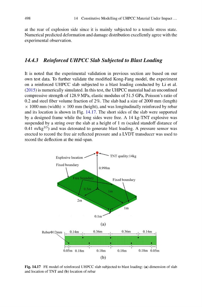
× 1000 mm (width) × 100 mm (height), and was longitudinally reinforced by rebar
and its location is shown in Fig. 14.17. The short sides of the slab were supported
by a designed frame while the long sides were free. A 14 kg-TNT explosive was
suspended by a string over the slab at a height of 1 m (scaled standoff distance of
0.41 m/kg
1/3 ) and was detonated to generate blast loading. A pressure sensor was
erected to record the free air reflected pressure and a LVDT transducer was used to
record the deflection at the mid-span.
Fig. 14.17 FE model of reinforced UHPCC slab subjected to blast loading: (a) dimension of slab
and location of TNT and (b) location of rebar
14 Constitutive Modelling of UHPCC Material Under Impact …
at the rear of explosion side since it is mainly subjected to a tensile stress state.
Numerical predicted deformation and damage distribution excellently agree with the
experimental observation.
14.4.3 Reinforced UHPCC Slab Subjected to Blast Loading
It is noted that the experimental validation in previous section are based on our
own test data. To further validate the modified Kong-Fang model, the experiment
on a reinforced UHPCC slab subjected to a blast loading conducted by Li et al.
(2015) is numerically simulated. In this test, the UHPCC material had an unconfined
compressive strength of 128.9 MPa, elastic modulus of 51.5 GPa, Poisson’s ratio of
0.2 and steel fiber volume fraction of 2%. The slab had a size of 2000 mm (length)
× 1000 mm (width) × 100 mm (height), and was longitudinally reinforced by rebar
and its location is shown in Fig. 14.17. The short sides of the slab were supported
by a designed frame while the long sides were free. A 14 kg-TNT explosive was
suspended by a string over the slab at a height of 1 m (scaled standoff distance of
0.41 m/kg
1/3 ) and was detonated to generate blast loading. A pressure sensor was
erected to record the free air reflected pressure and a LVDT transducer was used to
record the deflection at the mid-span.
Fig. 14.17 FE model of reinforced UHPCC slab subjected to blast loading: (a) dimension of slab
and location of TNT and (b) location of rebar