

496
14 Constitutive Modelling of UHPCC Material Under Impact …
simple supporting boundary. The reaction frame was made of high strength steel
and was fixed by the RC foundation. The cylindrical TNT charge had a diameter
of 270 mm, height of 280 mm and mass of 25 kg, which was placed at the center
of the column with a standoff distance of 0.45 m. The deflection-time history at the
mid-span of the column was recorded using the LVDT transducer.
The so-called ALE method is always used to simulate the interaction of blast
shock waves generated by explosive and structures, in which the explosive and air
are modelled as Eulerian grid and structures as Lagrangian grid and their interaction
are determined by an automatic coupling algorithm available in LS-DYNA. However,
this approach usually involves a huge number of elements and time-expensive. An
alternative approach is the so-called velocity method proposed by Remennikov and
Uy (2014). In this method, the blast loading generated by explosive is simplified as
a velocity loading applied on the structures as a boundary condition so that only the
UHPCC-FST column is needed to be modelled, which greatly improves computational efficiency. Recent study by Wu et al. (2020) demonstrated that the velocity
method is preferred for modelling the close-in explosion with the consideration of
both computational accuracy and efficiency.
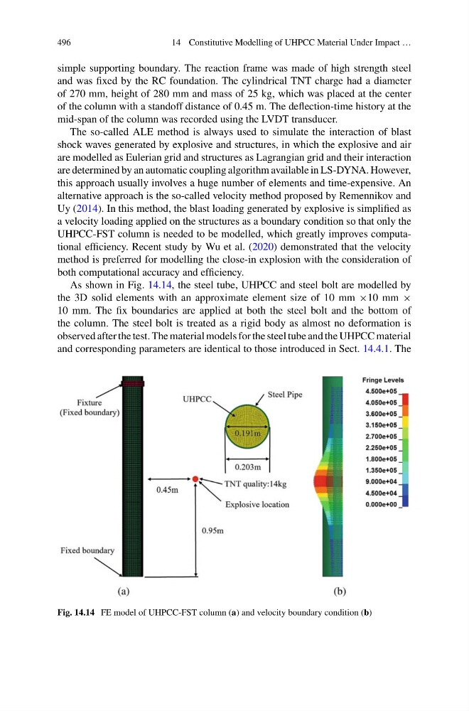
As shown in Fig. 14.14, the steel tube, UHPCC and steel bolt are modelled by
the 3D solid elements with an approximate element size of 10 mm ×10 mm ×
10 mm. The fix boundaries are applied at both the steel bolt and the bottom of
the column. The steel bolt is treated as a rigid body as almost no deformation is
observed after the test. The material models for the steel tube and the UHPCC material
and corresponding parameters are identical to those introduced in Sect. 14.4.1. The
Fig. 14.14 FE model of UHPCC-FST column (a) and velocity boundary condition (b)
14 Constitutive Modelling of UHPCC Material Under Impact …
simple supporting boundary. The reaction frame was made of high strength steel
and was fixed by the RC foundation. The cylindrical TNT charge had a diameter
of 270 mm, height of 280 mm and mass of 25 kg, which was placed at the center
of the column with a standoff distance of 0.45 m. The deflection-time history at the
mid-span of the column was recorded using the LVDT transducer.
The so-called ALE method is always used to simulate the interaction of blast
shock waves generated by explosive and structures, in which the explosive and air
are modelled as Eulerian grid and structures as Lagrangian grid and their interaction
are determined by an automatic coupling algorithm available in LS-DYNA. However,
this approach usually involves a huge number of elements and time-expensive. An
alternative approach is the so-called velocity method proposed by Remennikov and
Uy (2014). In this method, the blast loading generated by explosive is simplified as
a velocity loading applied on the structures as a boundary condition so that only the
UHPCC-FST column is needed to be modelled, which greatly improves computational efficiency. Recent study by Wu et al. (2020) demonstrated that the velocity
method is preferred for modelling the close-in explosion with the consideration of
both computational accuracy and efficiency.
As shown in Fig. 14.14, the steel tube, UHPCC and steel bolt are modelled by
the 3D solid elements with an approximate element size of 10 mm ×10 mm ×
10 mm. The fix boundaries are applied at both the steel bolt and the bottom of
the column. The steel bolt is treated as a rigid body as almost no deformation is
observed after the test. The material models for the steel tube and the UHPCC material
and corresponding parameters are identical to those introduced in Sect. 14.4.1. The
Fig. 14.14 FE model of UHPCC-FST column (a) and velocity boundary condition (b)