

14.4 Experimental Validation
493
0.000 0.005 0.010 0.015 0.020 0.025 0.030 0.035 0.040
0
100
200
300
400
500
Stress(MPa)
Strain
Experimental data
Original Kong-Fang model
Modified Kong-Fang model
(g)
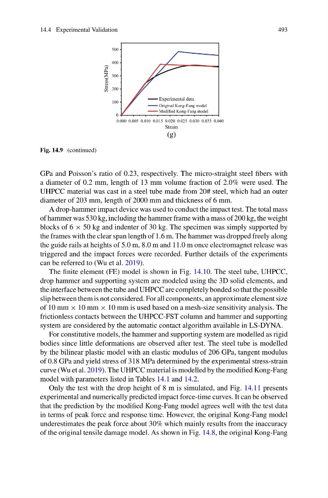
Fig. 14.9 (continued)
GPa and Poisson’s ratio of 0.23, respectively. The micro-straight steel fibers with
a diameter of 0.2 mm, length of 13 mm volume fraction of 2.0% were used. The
UHPCC material was cast in a steel tube made from 20# steel, which had an outer
diameter of 203 mm, length of 2000 mm and thickness of 6 mm.
A drop-hammer impact device was used to conduct the impact test. The total mass
of hammer was 530 kg, including the hammer frame with a mass of 200 kg, the weight
blocks of 6 × 50 kg and indenter of 30 kg. The specimen was simply supported by
the frames with the clear span length of 1.6 m. The hammer was dropped freely along
the guide rails at heights of 5.0 m, 8.0 m and 11.0 m once electromagnet release was
triggered and the impact forces were recorded. Further details of the experiments
can be referred to (Wu et al. 2019).
The finite element (FE) model is shown in Fig. 14.10. The steel tube, UHPCC,
drop hammer and supporting system are modeled using the 3D solid elements, and
the interface between the tube and UHPCC are completely bonded so that the possible
slip between them is not considered. For all components, an approximate element size
of 10 mm × 10 mm × 10 mm is used based on a mesh-size sensitivity analysis. The
frictionless contacts between the UHPCC-FST column and hammer and supporting
system are considered by the automatic contact algorithm available in LS-DYNA.
For constitutive models, the hammer and supporting system are modelled as rigid
bodies since little deformations are observed after test. The steel tube is modelled
by the bilinear plastic model with an elastic modulus of 206 GPa, tangent modulus
of 0.8 GPa and yield stress of 318 MPa determined by the experimental stress-strain
curve (Wu et al. 2019). The UHPCC material is modelled by the modified Kong-Fang
model with parameters listed in Tables 14.1 and 14.2.
Only the test with the drop height of 8 m is simulated, and Fig. 14.11 presents
experimental and numerically predicted impact force-time curves. It can be observed
that the prediction by the modified Kong-Fang model agrees well with the test data
in terms of peak force and response time. However, the original Kong-Fang model
underestimates the peak force about 30% which mainly results from the inaccuracy
of the original tensile damage model. As shown in Fig. 14.8, the original Kong-Fang
493
0.000 0.005 0.010 0.015 0.020 0.025 0.030 0.035 0.040
0
100
200
300
400
500
Stress(MPa)
Strain
Experimental data
Original Kong-Fang model
Modified Kong-Fang model
(g)
Fig. 14.9 (continued)
GPa and Poisson’s ratio of 0.23, respectively. The micro-straight steel fibers with
a diameter of 0.2 mm, length of 13 mm volume fraction of 2.0% were used. The
UHPCC material was cast in a steel tube made from 20# steel, which had an outer
diameter of 203 mm, length of 2000 mm and thickness of 6 mm.
A drop-hammer impact device was used to conduct the impact test. The total mass
of hammer was 530 kg, including the hammer frame with a mass of 200 kg, the weight
blocks of 6 × 50 kg and indenter of 30 kg. The specimen was simply supported by
the frames with the clear span length of 1.6 m. The hammer was dropped freely along
the guide rails at heights of 5.0 m, 8.0 m and 11.0 m once electromagnet release was
triggered and the impact forces were recorded. Further details of the experiments
can be referred to (Wu et al. 2019).
The finite element (FE) model is shown in Fig. 14.10. The steel tube, UHPCC,
drop hammer and supporting system are modeled using the 3D solid elements, and
the interface between the tube and UHPCC are completely bonded so that the possible
slip between them is not considered. For all components, an approximate element size
of 10 mm × 10 mm × 10 mm is used based on a mesh-size sensitivity analysis. The
frictionless contacts between the UHPCC-FST column and hammer and supporting
system are considered by the automatic contact algorithm available in LS-DYNA.
For constitutive models, the hammer and supporting system are modelled as rigid
bodies since little deformations are observed after test. The steel tube is modelled
by the bilinear plastic model with an elastic modulus of 206 GPa, tangent modulus
of 0.8 GPa and yield stress of 318 MPa determined by the experimental stress-strain
curve (Wu et al. 2019). The UHPCC material is modelled by the modified Kong-Fang
model with parameters listed in Tables 14.1 and 14.2.
Only the test with the drop height of 8 m is simulated, and Fig. 14.11 presents
experimental and numerically predicted impact force-time curves. It can be observed
that the prediction by the modified Kong-Fang model agrees well with the test data
in terms of peak force and response time. However, the original Kong-Fang model
underestimates the peak force about 30% which mainly results from the inaccuracy
of the original tensile damage model. As shown in Fig. 14.8, the original Kong-Fang