

14.3 Single Element Tests
489
14.3 Single Element Tests
The proposed tensile damage model is incorporated into the Kong-Fang model and
implemented into LS-DYNA through the user-defined material model (LSTC 2007).
To demonstrate the improved performances of the tensile damage model and the
modified set of parameters, numerical predictions by the original Kong-Fang model
using the automatic generated parameters suggested in (Kong et al. 2018a) and the
modified Kong-Fang model using the parameters in Table 14.1 and Table 14.2 at
material point level are compared using a single element.
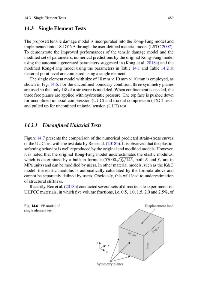
The single element model with size of 10 mm × 10 mm × 10 mm is employed, as
shown in Fig. 14.6. For the unconfined boundary condition, three symmetry planes
are used so that only 1/8 of a structure is modeled. When confinement is needed, the
three free planes are applied with hydrostatic pressure. The top face is pushed down
for unconfined uniaxial compression (UUC) and triaxial compression (TXC) tests,
and pulled up for unconfined uniaxial tension (UUT) test.
14.3.1 Unconfined Uniaxial Tests
Figure 14.7 presents the comparison of the numerical predicted strain-stress curves
of the UUC test with the test data by Ren et al. (2018b). It is observed that the plasticsoftening behavior is well reproduced by the original and modified models. However,
it is noted that the original Kong-Fang model underestimates the elastic modulus,
which is determined by a built-in formula (57000
√
f c /145, both E and f c are in
MPa units) and can be modified by users. In other material models, such as the K&C
model, the elastic modulus is automatically calculated by the formula above and
cannot be separately defined by users. Obviously, this will lead to underestimation
of structural stiffness.
Recently, Ren et al. (2018b) conducted several sets of direct tensile experiments on
UHPCC materials, in which five volume fractions, i.e. 0.5, 1.0, 1.5, 2.0 and 2.5%, of
Fig. 14.6 FE model of
single element test
489
14.3 Single Element Tests
The proposed tensile damage model is incorporated into the Kong-Fang model and
implemented into LS-DYNA through the user-defined material model (LSTC 2007).
To demonstrate the improved performances of the tensile damage model and the
modified set of parameters, numerical predictions by the original Kong-Fang model
using the automatic generated parameters suggested in (Kong et al. 2018a) and the
modified Kong-Fang model using the parameters in Table 14.1 and Table 14.2 at
material point level are compared using a single element.
The single element model with size of 10 mm × 10 mm × 10 mm is employed, as
shown in Fig. 14.6. For the unconfined boundary condition, three symmetry planes
are used so that only 1/8 of a structure is modeled. When confinement is needed, the
three free planes are applied with hydrostatic pressure. The top face is pushed down
for unconfined uniaxial compression (UUC) and triaxial compression (TXC) tests,
and pulled up for unconfined uniaxial tension (UUT) test.
14.3.1 Unconfined Uniaxial Tests
Figure 14.7 presents the comparison of the numerical predicted strain-stress curves
of the UUC test with the test data by Ren et al. (2018b). It is observed that the plasticsoftening behavior is well reproduced by the original and modified models. However,
it is noted that the original Kong-Fang model underestimates the elastic modulus,
which is determined by a built-in formula (57000
√
f c /145, both E and f c are in
MPa units) and can be modified by users. In other material models, such as the K&C
model, the elastic modulus is automatically calculated by the formula above and
cannot be separately defined by users. Obviously, this will lead to underestimation
of structural stiffness.
Recently, Ren et al. (2018b) conducted several sets of direct tensile experiments on
UHPCC materials, in which five volume fractions, i.e. 0.5, 1.0, 1.5, 2.0 and 2.5%, of
Fig. 14.6 FE model of
single element test