

486
14 Constitutive Modelling of UHPCC Material Under Impact …
1E-11 1E-9 1E-7 1E-5 1E-3 0.1
10 1000
0
2
4
6
8
10
12
14
DIF
t
Log10 (strain-rate)
Pyo et al. (2016)
Park et al. (2016)
Tran et al. (2015)
Ranade et al. (2015)
Pyo et al. (2015)
Fujikake et al. (2006)
Su et al. (2016b)
Ren et al. (2017)
Su et al.(2016a)
Cadoni and Forni (2016)
Wille et al. (2014)
Tran and Kim (2017)
Eq.(14.20)
1E-7 1E-6 1E-5 1E-4 0.001 0.01 0.1 1 10 100 1000
0.5
1.0
1.5
2.0
2.5
3.0
3.5
4.0
4.5
Ren et al. (2017)
Clark. (2013)
Li et al. (2016)
Hassan and Wille (2018)
Hao and Hao (2013)
DIF
c
Log10 (strain-rate)
Eq.(14.21)
(a)
(b)
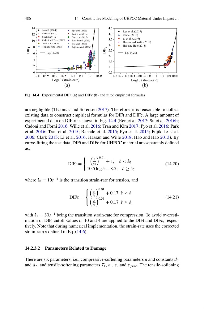
Fig. 14.4 Experimental DIFt (a) and DIFc (b) and fitted empirical formulas
are negligible (Thaomas and Sorensen 2017). Therefore, it is reasonable to collect
existing data to construct empirical formulas for DIFt and DIFc. A large amount of
experimental data on DIF-˙ ε is shown in Fig. 14.4 (Ren et al. 2017; Su et al. 2016b;
Cadoni and Forni 2016; Wille et al. 2016; Tran and Kim 2017; Pyo et al. 2016; Park
et al. 2016; Tran et al. 2015; Ranade et al. 2015; Pyo et al. 2015; Fujikake et al.
2006; Clark 2013; Li et al. 2016; Hassan and Wille 2018; Hao and Hao 2013). By
curve-fitting the test data, DIFt and DIFc for UHPCC material are separately defined
as,
DIFt =
˙
ε
˙
ε 0
0.01 + 1, ˙
ε < ˙
ε 0
10.5 log ˙
ε − 8.5, ˙
ε ≥ ˙
ε 0
(14.20)
where ˙
ε 0 = 10s
−1 is the transition strain-rate for tension, and
DIFc =
⎧
⎨
⎩
˙
ε
˙
ε 1
0.01 + 0.17, ˙
ε < ˙
ε 1
˙
ε
˙
ε 1
0.33 + 0.17, ˙
ε ≥ ˙
ε 1
(14.21)
with ˙
ε 1 = 30s
−1 being the transition strain-rate for compression. To avoid overestimation of DIF, cutoff values of 10 and 4 are applied to the DIFt and DIFc, respectively. Note that during numerical implementation, the strain-rate uses the corrected
strain-rate ¯ ˙
ε defined in Eq. (14.6).
14.2.3.2 Parameters Related to Damage
There are six parameters, i.e., compressive-softening parameters a and constants d 1
and d 2 , and tensile-softening parameters T 1 , ε 1 , ε 2 and ε f rac . The tensile-softening
14 Constitutive Modelling of UHPCC Material Under Impact …
1E-11 1E-9 1E-7 1E-5 1E-3 0.1
10 1000
0
2
4
6
8
10
12
14
DIF
t
Log10 (strain-rate)
Pyo et al. (2016)
Park et al. (2016)
Tran et al. (2015)
Ranade et al. (2015)
Pyo et al. (2015)
Fujikake et al. (2006)
Su et al. (2016b)
Ren et al. (2017)
Su et al.(2016a)
Cadoni and Forni (2016)
Wille et al. (2014)
Tran and Kim (2017)
Eq.(14.20)
1E-7 1E-6 1E-5 1E-4 0.001 0.01 0.1 1 10 100 1000
0.5
1.0
1.5
2.0
2.5
3.0
3.5
4.0
4.5
Ren et al. (2017)
Clark. (2013)
Li et al. (2016)
Hassan and Wille (2018)
Hao and Hao (2013)
DIF
c
Log10 (strain-rate)
Eq.(14.21)
(a)
(b)
Fig. 14.4 Experimental DIFt (a) and DIFc (b) and fitted empirical formulas
are negligible (Thaomas and Sorensen 2017). Therefore, it is reasonable to collect
existing data to construct empirical formulas for DIFt and DIFc. A large amount of
experimental data on DIF-˙ ε is shown in Fig. 14.4 (Ren et al. 2017; Su et al. 2016b;
Cadoni and Forni 2016; Wille et al. 2016; Tran and Kim 2017; Pyo et al. 2016; Park
et al. 2016; Tran et al. 2015; Ranade et al. 2015; Pyo et al. 2015; Fujikake et al.
2006; Clark 2013; Li et al. 2016; Hassan and Wille 2018; Hao and Hao 2013). By
curve-fitting the test data, DIFt and DIFc for UHPCC material are separately defined
as,
DIFt =
˙
ε
˙
ε 0
0.01 + 1, ˙
ε < ˙
ε 0
10.5 log ˙
ε − 8.5, ˙
ε ≥ ˙
ε 0
(14.20)
where ˙
ε 0 = 10s
−1 is the transition strain-rate for tension, and
DIFc =
⎧
⎨
⎩
˙
ε
˙
ε 1
0.01 + 0.17, ˙
ε < ˙
ε 1
˙
ε
˙
ε 1
0.33 + 0.17, ˙
ε ≥ ˙
ε 1
(14.21)
with ˙
ε 1 = 30s
−1 being the transition strain-rate for compression. To avoid overestimation of DIF, cutoff values of 10 and 4 are applied to the DIFt and DIFc, respectively. Note that during numerical implementation, the strain-rate uses the corrected
strain-rate ¯ ˙
ε defined in Eq. (14.6).
14.2.3.2 Parameters Related to Damage
There are six parameters, i.e., compressive-softening parameters a and constants d 1
and d 2 , and tensile-softening parameters T 1 , ε 1 , ε 2 and ε f rac . The tensile-softening