

408
12 Experimental Study on the Residual Seismic Resistance of UHPCC …
from the explosive were transmitted into the foundation due to the larger charge
weight of explosive.
From the above analysis, in the present contact detonation scenario, it can be
concluded that the UHPCC-FST column suffered the localized damage with the
formation of crater beneath the explosive, and there was almost no overall response
in the columns. The repeatability of the present test is validated and the dimensions
of the local crater are enlarged with increasing the charge weight. In the following
section, the seismic resistance of these four post-blast UHPCC-FST and two intact
column specimens was experimentally studied, and the influencing factors, such as
damaged degree of specimens after blast and cyclic loading direction are considered.
12.4 Low-Frequency Cyclic Loading Test
12.4.1 Test Setup
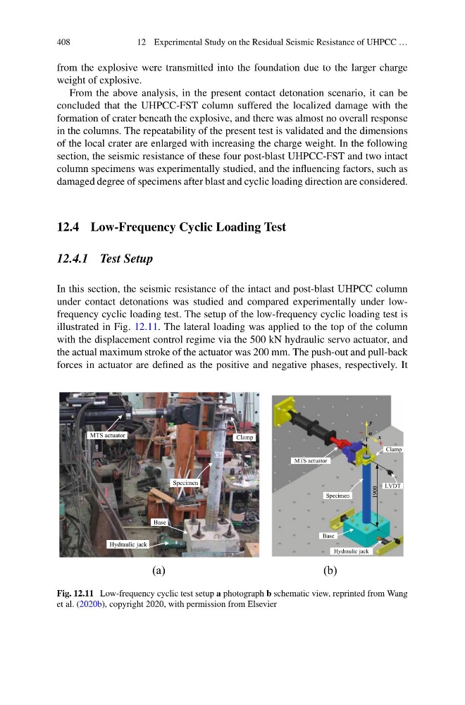
In this section, the seismic resistance of the intact and post-blast UHPCC column
under contact detonations was studied and compared experimentally under lowfrequency cyclic loading test. The setup of the low-frequency cyclic loading test is
illustrated in Fig. 12.11. The lateral loading was applied to the top of the column
with the displacement control regime via the 500 kN hydraulic servo actuator, and
the actual maximum stroke of the actuator was 200 mm. The push-out and pull-back
forces in actuator are defined as the positive and negative phases, respectively. It
Hydraulic jack
MTS actuator
Clamp
Specimen
Base
1900
LVDT
+
- o x
y
Hydraulic jack
MTS actuator
Clamp
Specimen
Base
(a)
(b)
Fig. 12.11 Low-frequency cyclic test setup a photograph b schematic view, reprinted from Wang
et al. (2020b), copyright 2020, with permission from Elsevier
12 Experimental Study on the Residual Seismic Resistance of UHPCC …
from the explosive were transmitted into the foundation due to the larger charge
weight of explosive.
From the above analysis, in the present contact detonation scenario, it can be
concluded that the UHPCC-FST column suffered the localized damage with the
formation of crater beneath the explosive, and there was almost no overall response
in the columns. The repeatability of the present test is validated and the dimensions
of the local crater are enlarged with increasing the charge weight. In the following
section, the seismic resistance of these four post-blast UHPCC-FST and two intact
column specimens was experimentally studied, and the influencing factors, such as
damaged degree of specimens after blast and cyclic loading direction are considered.
12.4 Low-Frequency Cyclic Loading Test
12.4.1 Test Setup
In this section, the seismic resistance of the intact and post-blast UHPCC column
under contact detonations was studied and compared experimentally under lowfrequency cyclic loading test. The setup of the low-frequency cyclic loading test is
illustrated in Fig. 12.11. The lateral loading was applied to the top of the column
with the displacement control regime via the 500 kN hydraulic servo actuator, and
the actual maximum stroke of the actuator was 200 mm. The push-out and pull-back
forces in actuator are defined as the positive and negative phases, respectively. It
Hydraulic jack
MTS actuator
Clamp
Specimen
Base
1900
LVDT
+
- o x
y
Hydraulic jack
MTS actuator
Clamp
Specimen
Base
(a)
(b)
Fig. 12.11 Low-frequency cyclic test setup a photograph b schematic view, reprinted from Wang
et al. (2020b), copyright 2020, with permission from Elsevier