

404
12 Experimental Study on the Residual Seismic Resistance of UHPCC …
TNT charge
250
1900
TNT charge
250
1900
Jack of detonator
1kg
2kg
3kg
116
121
95
92
(a)
(b)
(c)
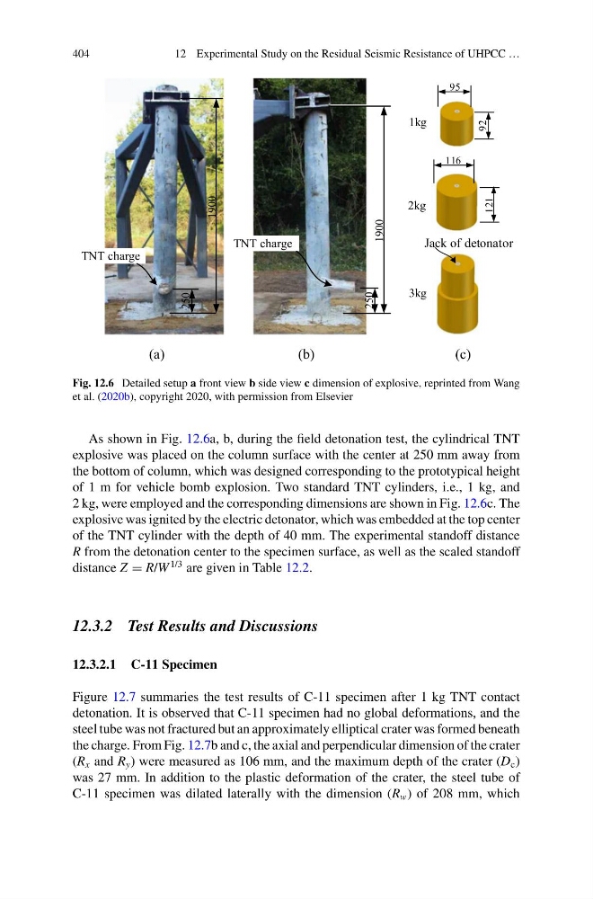
Fig. 12.6 Detailed setup a front view b side view c dimension of explosive, reprinted from Wang
et al. (2020b), copyright 2020, with permission from Elsevier
As shown in Fig. 12.6a, b, during the field detonation test, the cylindrical TNT
explosive was placed on the column surface with the center at 250 mm away from
the bottom of column, which was designed corresponding to the prototypical height
of 1 m for vehicle bomb explosion. Two standard TNT cylinders, i.e., 1 kg, and
2 kg, were employed and the corresponding dimensions are shown in Fig. 12.6c. The
explosive was ignited by the electric detonator, which was embedded at the top center
of the TNT cylinder with the depth of 40 mm. The experimental standoff distance
R from the detonation center to the specimen surface, as well as the scaled standoff
distance Z = R/W
1/3 are given in Table 12.2.
12.3.2 Test Results and Discussions
12.3.2.1 C-11 Specimen
Figure 12.7 summaries the test results of C-11 specimen after 1 kg TNT contact
detonation. It is observed that C-11 specimen had no global deformations, and the
steel tube was not fractured but an approximately elliptical crater was formed beneath
the charge. From Fig. 12.7b and c, the axial and perpendicular dimension of the crater
(R x and R y ) were measured as 106 mm, and the maximum depth of the crater (D c )
was 27 mm. In addition to the plastic deformation of the crater, the steel tube of
C-11 specimen was dilated laterally with the dimension (R w ) of 208 mm, which
12 Experimental Study on the Residual Seismic Resistance of UHPCC …
TNT charge
250
1900
TNT charge
250
1900
Jack of detonator
1kg
2kg
3kg
116
121
95
92
(a)
(b)
(c)
Fig. 12.6 Detailed setup a front view b side view c dimension of explosive, reprinted from Wang
et al. (2020b), copyright 2020, with permission from Elsevier
As shown in Fig. 12.6a, b, during the field detonation test, the cylindrical TNT
explosive was placed on the column surface with the center at 250 mm away from
the bottom of column, which was designed corresponding to the prototypical height
of 1 m for vehicle bomb explosion. Two standard TNT cylinders, i.e., 1 kg, and
2 kg, were employed and the corresponding dimensions are shown in Fig. 12.6c. The
explosive was ignited by the electric detonator, which was embedded at the top center
of the TNT cylinder with the depth of 40 mm. The experimental standoff distance
R from the detonation center to the specimen surface, as well as the scaled standoff
distance Z = R/W
1/3 are given in Table 12.2.
12.3.2 Test Results and Discussions
12.3.2.1 C-11 Specimen
Figure 12.7 summaries the test results of C-11 specimen after 1 kg TNT contact
detonation. It is observed that C-11 specimen had no global deformations, and the
steel tube was not fractured but an approximately elliptical crater was formed beneath
the charge. From Fig. 12.7b and c, the axial and perpendicular dimension of the crater
(R x and R y ) were measured as 106 mm, and the maximum depth of the crater (D c )
was 27 mm. In addition to the plastic deformation of the crater, the steel tube of
C-11 specimen was dilated laterally with the dimension (R w ) of 208 mm, which