

12.2 UHPCC-FST Specimens
403
(denoted parallel in Table 12.2), while for other specimens, the loading direction was
perpendicular to the detonation face (denoted perpendicular in Table 12.2).
12.3 Contact Explosion Test
12.3.1 Test Setup
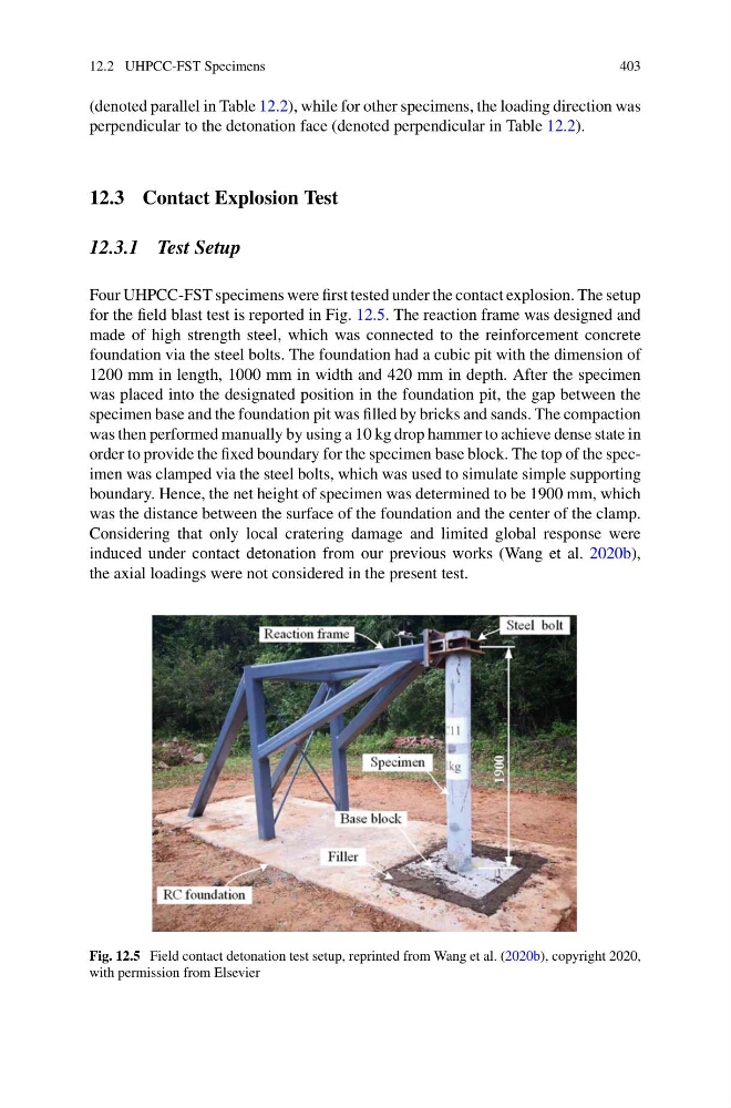
Four UHPCC-FST specimens were first tested under the contact explosion. The setup
for the field blast test is reported in Fig. 12.5. The reaction frame was designed and
made of high strength steel, which was connected to the reinforcement concrete
foundation via the steel bolts. The foundation had a cubic pit with the dimension of
1200 mm in length, 1000 mm in width and 420 mm in depth. After the specimen
was placed into the designated position in the foundation pit, the gap between the
specimen base and the foundation pit was filled by bricks and sands. The compaction
was then performed manually by using a 10 kg drop hammer to achieve dense state in
order to provide the fixed boundary for the specimen base block. The top of the specimen was clamped via the steel bolts, which was used to simulate simple supporting
boundary. Hence, the net height of specimen was determined to be 1900 mm, which
was the distance between the surface of the foundation and the center of the clamp.
Considering that only local cratering damage and limited global response were
induced under contact detonation from our previous works (Wang et al. 2020b),
the axial loadings were not considered in the present test.
Fig. 12.5 Field contact detonation test setup, reprinted from Wang et al. (2020b), copyright 2020,
with permission from Elsevier
403
(denoted parallel in Table 12.2), while for other specimens, the loading direction was
perpendicular to the detonation face (denoted perpendicular in Table 12.2).
12.3 Contact Explosion Test
12.3.1 Test Setup
Four UHPCC-FST specimens were first tested under the contact explosion. The setup
for the field blast test is reported in Fig. 12.5. The reaction frame was designed and
made of high strength steel, which was connected to the reinforcement concrete
foundation via the steel bolts. The foundation had a cubic pit with the dimension of
1200 mm in length, 1000 mm in width and 420 mm in depth. After the specimen
was placed into the designated position in the foundation pit, the gap between the
specimen base and the foundation pit was filled by bricks and sands. The compaction
was then performed manually by using a 10 kg drop hammer to achieve dense state in
order to provide the fixed boundary for the specimen base block. The top of the specimen was clamped via the steel bolts, which was used to simulate simple supporting
boundary. Hence, the net height of specimen was determined to be 1900 mm, which
was the distance between the surface of the foundation and the center of the clamp.
Considering that only local cratering damage and limited global response were
induced under contact detonation from our previous works (Wang et al. 2020b),
the axial loadings were not considered in the present test.
Fig. 12.5 Field contact detonation test setup, reprinted from Wang et al. (2020b), copyright 2020,
with permission from Elsevier