

402
12 Experimental Study on the Residual Seismic Resistance of UHPCC …
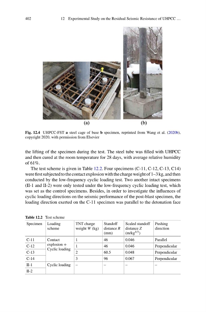
Fig. 12.4 UHPCC-FST a steel cage of base b specimen, reprinted from Wang et al. (2020b),
copyright 2020, with permission from Elsevier
the lifting of the specimen during the test. The steel tube was filled with UHPCC
and then cured at the room temperature for 28 days, with average relative humidity
of 61%.
The test scheme is given in Table 12.2. Four specimens (C-11, C-12, C-13, C14)
were first subjected to the contact explosion with the charge weight of 1–3 kg, and then
conducted by the low-frequency cyclic loading test. Two another intact specimens
(II-1 and II-2) were only tested under the low-frequency cyclic loading test, which
was set as the control specimens. Besides, in order to investigate the influences of
cyclic loading directions on the seismic performance of the post-blast specimen, the
loading direction exerted on the C-11 specimen was parallel to the detonation face
Table 12.2 Test scheme
Specimen Loading
scheme
TNT charge
weight W (kg)
Standoff
distance R
(mm)
Scaled standoff
distance Z
(m/kg 1/3 )
Pushing
direction
C-11
Contact
explosion +
Cyclic loading
1
46
0.046
Parallel
C-12
1
46
0.046
Perpendicular
C-13
2
60.5
0.048
Perpendicular
C-14
3
96
0.067
Perpendicular
II-1
Cyclic loading –
–
–
–
II-2
12 Experimental Study on the Residual Seismic Resistance of UHPCC …
Fig. 12.4 UHPCC-FST a steel cage of base b specimen, reprinted from Wang et al. (2020b),
copyright 2020, with permission from Elsevier
the lifting of the specimen during the test. The steel tube was filled with UHPCC
and then cured at the room temperature for 28 days, with average relative humidity
of 61%.
The test scheme is given in Table 12.2. Four specimens (C-11, C-12, C-13, C14)
were first subjected to the contact explosion with the charge weight of 1–3 kg, and then
conducted by the low-frequency cyclic loading test. Two another intact specimens
(II-1 and II-2) were only tested under the low-frequency cyclic loading test, which
was set as the control specimens. Besides, in order to investigate the influences of
cyclic loading directions on the seismic performance of the post-blast specimen, the
loading direction exerted on the C-11 specimen was parallel to the detonation face
Table 12.2 Test scheme
Specimen Loading
scheme
TNT charge
weight W (kg)
Standoff
distance R
(mm)
Scaled standoff
distance Z
(m/kg 1/3 )
Pushing
direction
C-11
Contact
explosion +
Cyclic loading
1
46
0.046
Parallel
C-12
1
46
0.046
Perpendicular
C-13
2
60.5
0.048
Perpendicular
C-14
3
96
0.067
Perpendicular
II-1
Cyclic loading –
–
–
–
II-2