

12.3 Contact Explosion Test
405
248
Ry
Rx
Rw
Dc
(a)
(b)
(c)
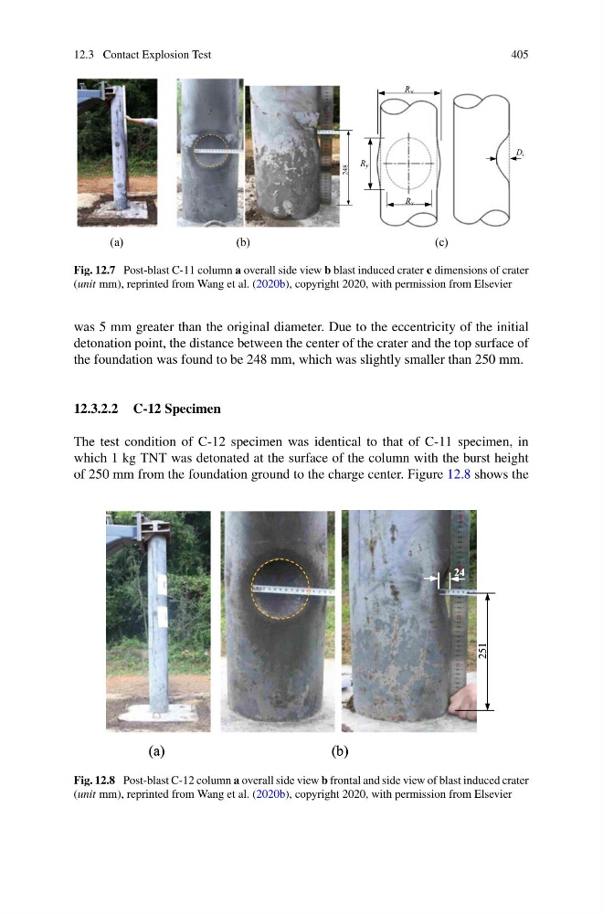
Fig. 12.7 Post-blast C-11 column a overall side view b blast induced crater c dimensions of crater
(unit mm), reprinted from Wang et al. (2020b), copyright 2020, with permission from Elsevier
was 5 mm greater than the original diameter. Due to the eccentricity of the initial
detonation point, the distance between the center of the crater and the top surface of
the foundation was found to be 248 mm, which was slightly smaller than 250 mm.
12.3.2.2 C-12 Specimen
The test condition of C-12 specimen was identical to that of C-11 specimen, in
which 1 kg TNT was detonated at the surface of the column with the burst height
of 250 mm from the foundation ground to the charge center. Figure 12.8 shows the
251
24
(b)
251
24
(b)
(a) (a)
Fig. 12.8 Post-blast C-12 column a overall side view b frontal and side view of blast induced crater
(unit mm), reprinted from Wang et al. (2020b), copyright 2020, with permission from Elsevier
405
248
Ry
Rx
Rw
Dc
(a)
(b)
(c)
Fig. 12.7 Post-blast C-11 column a overall side view b blast induced crater c dimensions of crater
(unit mm), reprinted from Wang et al. (2020b), copyright 2020, with permission from Elsevier
was 5 mm greater than the original diameter. Due to the eccentricity of the initial
detonation point, the distance between the center of the crater and the top surface of
the foundation was found to be 248 mm, which was slightly smaller than 250 mm.
12.3.2.2 C-12 Specimen
The test condition of C-12 specimen was identical to that of C-11 specimen, in
which 1 kg TNT was detonated at the surface of the column with the burst height
of 250 mm from the foundation ground to the charge center. Figure 12.8 shows the
251
24
(b)
251
24
(b)
(a) (a)
Fig. 12.8 Post-blast C-12 column a overall side view b frontal and side view of blast induced crater
(unit mm), reprinted from Wang et al. (2020b), copyright 2020, with permission from Elsevier