

11.3 Analytical Methods for Predicting the Dynamic Responses …
383
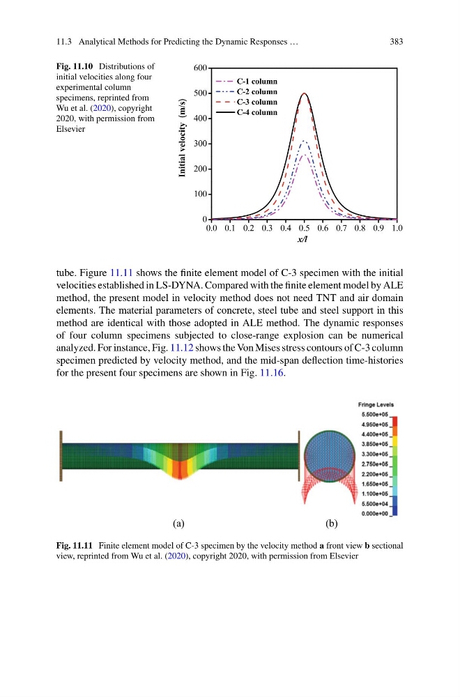
Fig. 11.10 Distributions of
initial velocities along four
experimental column
specimens, reprinted from
Wu et al. (2020), copyright
2020, with permission from
Elsevier
0.0 0.1 0.2 0.3 0.4 0.5 0.6 0.7 0.8 0.9 1.0
0
100
200
300
400
500
600
C-1 column
C-2 column
C-3 column
C-4 column
Initial velocity
(m/s)
x/l
tube. Figure 11.11 shows the finite element model of C-3 specimen with the initial
velocities established in LS-DYNA. Compared with the finite element model by ALE
method, the present model in velocity method does not need TNT and air domain
elements. The material parameters of concrete, steel tube and steel support in this
method are identical with those adopted in ALE method. The dynamic responses
of four column specimens subjected to close-range explosion can be numerical
analyzed. For instance, Fig. 11.12 shows the Von Mises stress contours of C-3 column
specimen predicted by velocity method, and the mid-span deflection time-histories
for the present four specimens are shown in Fig. 11.16.
(a)
(b)
Fig. 11.11 Finite element model of C-3 specimen by the velocity method a front view b sectional
view, reprinted from Wu et al. (2020), copyright 2020, with permission from Elsevier
383
Fig. 11.10 Distributions of
initial velocities along four
experimental column
specimens, reprinted from
Wu et al. (2020), copyright
2020, with permission from
Elsevier
0.0 0.1 0.2 0.3 0.4 0.5 0.6 0.7 0.8 0.9 1.0
0
100
200
300
400
500
600
C-1 column
C-2 column
C-3 column
C-4 column
Initial velocity
(m/s)
x/l
tube. Figure 11.11 shows the finite element model of C-3 specimen with the initial
velocities established in LS-DYNA. Compared with the finite element model by ALE
method, the present model in velocity method does not need TNT and air domain
elements. The material parameters of concrete, steel tube and steel support in this
method are identical with those adopted in ALE method. The dynamic responses
of four column specimens subjected to close-range explosion can be numerical
analyzed. For instance, Fig. 11.12 shows the Von Mises stress contours of C-3 column
specimen predicted by velocity method, and the mid-span deflection time-histories
for the present four specimens are shown in Fig. 11.16.
(a)
(b)
Fig. 11.11 Finite element model of C-3 specimen by the velocity method a front view b sectional
view, reprinted from Wu et al. (2020), copyright 2020, with permission from Elsevier