

350
10 Residual Axial Capacity of UHPCC-FST Column Under …
adopted in the numerical simulation for the steel tube material, the fracturing behavior
of the steel tube in the C-3 column is not fully reproduced.
10.7.2 Residual Axial Capacity and Failure Mode of Columns
10.7.2.1 Intact Columns (I-8, I-9)
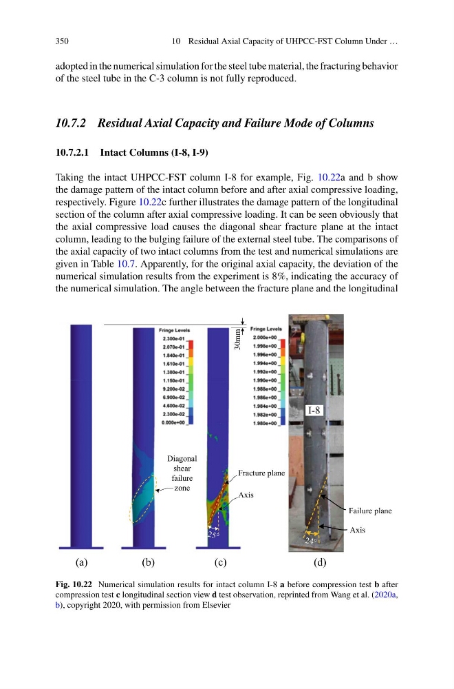
Taking the intact UHPCC-FST column I-8 for example, Fig. 10.22a and b show
the damage pattern of the intact column before and after axial compressive loading,
respectively. Figure 10.22c further illustrates the damage pattern of the longitudinal
section of the column after axial compressive loading. It can be seen obviously that
the axial compressive load causes the diagonal shear fracture plane at the intact
column, leading to the bulging failure of the external steel tube. The comparisons of
the axial capacity of two intact columns from the test and numerical simulations are
given in Table 10.7. Apparently, for the original axial capacity, the deviation of the
numerical simulation results from the experiment is 8%, indicating the accuracy of
the numerical simulation. The angle between the fracture plane and the longitudinal
30mm
Diagonal
shear
failure
zone
Axis
Fracture plane
I-8
Failure plane
Axis
(a)
(b)
(c)
(d)
Fig. 10.22 Numerical simulation results for intact column I-8 a before compression test b after
compression test c longitudinal section view d test observation, reprinted from Wang et al. (2020a,
b), copyright 2020, with permission from Elsevier
10 Residual Axial Capacity of UHPCC-FST Column Under …
adopted in the numerical simulation for the steel tube material, the fracturing behavior
of the steel tube in the C-3 column is not fully reproduced.
10.7.2 Residual Axial Capacity and Failure Mode of Columns
10.7.2.1 Intact Columns (I-8, I-9)
Taking the intact UHPCC-FST column I-8 for example, Fig. 10.22a and b show
the damage pattern of the intact column before and after axial compressive loading,
respectively. Figure 10.22c further illustrates the damage pattern of the longitudinal
section of the column after axial compressive loading. It can be seen obviously that
the axial compressive load causes the diagonal shear fracture plane at the intact
column, leading to the bulging failure of the external steel tube. The comparisons of
the axial capacity of two intact columns from the test and numerical simulations are
given in Table 10.7. Apparently, for the original axial capacity, the deviation of the
numerical simulation results from the experiment is 8%, indicating the accuracy of
the numerical simulation. The angle between the fracture plane and the longitudinal
30mm
Diagonal
shear
failure
zone
Axis
Fracture plane
I-8
Failure plane
Axis
(a)
(b)
(c)
(d)
Fig. 10.22 Numerical simulation results for intact column I-8 a before compression test b after
compression test c longitudinal section view d test observation, reprinted from Wang et al. (2020a,
b), copyright 2020, with permission from Elsevier