

336
10 Residual Axial Capacity of UHPCC-FST Column Under …
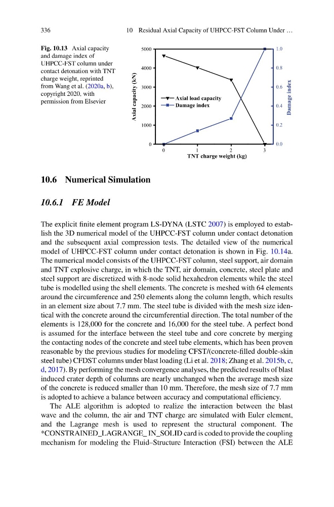
Fig. 10.13 Axial capacity
and damage index of
UHPCC-FST column under
contact detonation with TNT
charge weight, reprinted
from Wang et al. (2020a, b),
copyright 2020, with
permission from Elsevier
0
1
2
3
0
1000
2000
3000
4000
5000
Axial load capacity
Damage index
TNT charge weight (kg)
Axial capacity (kN)
0.0
0.2
0.4
0.6
0.8
1.0
Damage index
10.6 Numerical Simulation
10.6.1 FE Model
The explicit finite element program LS-DYNA (LSTC 2007) is employed to establish the 3D numerical model of the UHPCC-FST column under contact detonation
and the subsequent axial compression tests. The detailed view of the numerical
model of UHPCC-FST column under contact detonation is shown in Fig. 10.14a.
The numerical model consists of the UHPCC-FST column, steel support, air domain
and TNT explosive charge, in which the TNT, air domain, concrete, steel plate and
steel support are discretized with 8-node solid hexahedron elements while the steel
tube is modelled using the shell elements. The concrete is meshed with 64 elements
around the circumference and 250 elements along the column length, which results
in an element size about 7.7 mm. The steel tube is divided with the mesh size identical with the concrete around the circumferential direction. The total number of the
elements is 128,000 for the concrete and 16,000 for the steel tube. A perfect bond
is assumed for the interface between the steel tube and core concrete by merging
the contacting nodes of the concrete and steel tube elements, which has been proven
reasonable by the previous studies for modeling CFST/(concrete-filled double-skin
steel tube) CFDST columns under blast loading (Li et al. 2018; Zhang et al. 2015b, c,
d, 2017). By performing the mesh convergence analyses, the predicted results of blast
induced crater depth of columns are nearly unchanged when the average mesh size
of the concrete is reduced smaller than 10 mm. Therefore, the mesh size of 7.7 mm
is adopted to achieve a balance between accuracy and computational efficiency.
The ALE algorithm is adopted to realize the interaction between the blast
wave and the column, the air and TNT charge are simulated with Euler element,
and the Lagrange mesh is used to represent the structural component. The
*CONSTRAINED_LAGRANGE_ IN_SOLID card is coded to provide the coupling
mechanism for modeling the Fluid–Structure Interaction (FSI) between the ALE
10 Residual Axial Capacity of UHPCC-FST Column Under …
Fig. 10.13 Axial capacity
and damage index of
UHPCC-FST column under
contact detonation with TNT
charge weight, reprinted
from Wang et al. (2020a, b),
copyright 2020, with
permission from Elsevier
0
1
2
3
0
1000
2000
3000
4000
5000
Axial load capacity
Damage index
TNT charge weight (kg)
Axial capacity (kN)
0.0
0.2
0.4
0.6
0.8
1.0
Damage index
10.6 Numerical Simulation
10.6.1 FE Model
The explicit finite element program LS-DYNA (LSTC 2007) is employed to establish the 3D numerical model of the UHPCC-FST column under contact detonation
and the subsequent axial compression tests. The detailed view of the numerical
model of UHPCC-FST column under contact detonation is shown in Fig. 10.14a.
The numerical model consists of the UHPCC-FST column, steel support, air domain
and TNT explosive charge, in which the TNT, air domain, concrete, steel plate and
steel support are discretized with 8-node solid hexahedron elements while the steel
tube is modelled using the shell elements. The concrete is meshed with 64 elements
around the circumference and 250 elements along the column length, which results
in an element size about 7.7 mm. The steel tube is divided with the mesh size identical with the concrete around the circumferential direction. The total number of the
elements is 128,000 for the concrete and 16,000 for the steel tube. A perfect bond
is assumed for the interface between the steel tube and core concrete by merging
the contacting nodes of the concrete and steel tube elements, which has been proven
reasonable by the previous studies for modeling CFST/(concrete-filled double-skin
steel tube) CFDST columns under blast loading (Li et al. 2018; Zhang et al. 2015b, c,
d, 2017). By performing the mesh convergence analyses, the predicted results of blast
induced crater depth of columns are nearly unchanged when the average mesh size
of the concrete is reduced smaller than 10 mm. Therefore, the mesh size of 7.7 mm
is adopted to achieve a balance between accuracy and computational efficiency.
The ALE algorithm is adopted to realize the interaction between the blast
wave and the column, the air and TNT charge are simulated with Euler element,
and the Lagrange mesh is used to represent the structural component. The
*CONSTRAINED_LAGRANGE_ IN_SOLID card is coded to provide the coupling
mechanism for modeling the Fluid–Structure Interaction (FSI) between the ALE