

10.5 Axial Compression Test
335
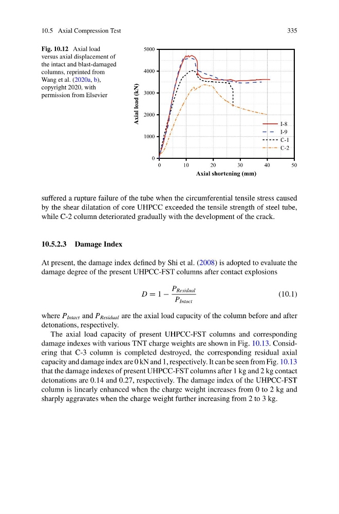
Fig. 10.12 Axial load
versus axial displacement of
the intact and blast-damaged
columns, reprinted from
Wang et al. (2020a, b),
copyright 2020, with
permission from Elsevier
0
1 0
2 0
3 0
4 0
5 0
0
1000
2000
3000
4000
5000
Axial load (kN)
Axial shortening (mm)
I-8
I-9
C-1
C-2
suffered a rupture failure of the tube when the circumferential tensile stress caused
by the shear dilatation of core UHPCC exceeded the tensile strength of steel tube,
while C-2 column deteriorated gradually with the development of the crack.
10.5.2.3 Damage Index
At present, the damage index defined by Shi et al. (2008) is adopted to evaluate the
damage degree of the present UHPCC-FST columns after contact explosions
D = 1 −
P Residual
P Intact
(10.1)
where P Intact and P Residual are the axial load capacity of the column before and after
detonations, respectively.
The axial load capacity of present UHPCC-FST columns and corresponding
damage indexes with various TNT charge weights are shown in Fig. 10.13. Considering that C-3 column is completed destroyed, the corresponding residual axial
capacity and damage index are 0 kN and 1, respectively. It can be seen from Fig. 10.13
that the damage indexes of present UHPCC-FST columns after 1 kg and 2 kg contact
detonations are 0.14 and 0.27, respectively. The damage index of the UHPCC-FST
column is linearly enhanced when the charge weight increases from 0 to 2 kg and
sharply aggravates when the charge weight further increasing from 2 to 3 kg.
335
Fig. 10.12 Axial load
versus axial displacement of
the intact and blast-damaged
columns, reprinted from
Wang et al. (2020a, b),
copyright 2020, with
permission from Elsevier
0
1 0
2 0
3 0
4 0
5 0
0
1000
2000
3000
4000
5000
Axial load (kN)
Axial shortening (mm)
I-8
I-9
C-1
C-2
suffered a rupture failure of the tube when the circumferential tensile stress caused
by the shear dilatation of core UHPCC exceeded the tensile strength of steel tube,
while C-2 column deteriorated gradually with the development of the crack.
10.5.2.3 Damage Index
At present, the damage index defined by Shi et al. (2008) is adopted to evaluate the
damage degree of the present UHPCC-FST columns after contact explosions
D = 1 −
P Residual
P Intact
(10.1)
where P Intact and P Residual are the axial load capacity of the column before and after
detonations, respectively.
The axial load capacity of present UHPCC-FST columns and corresponding
damage indexes with various TNT charge weights are shown in Fig. 10.13. Considering that C-3 column is completed destroyed, the corresponding residual axial
capacity and damage index are 0 kN and 1, respectively. It can be seen from Fig. 10.13
that the damage indexes of present UHPCC-FST columns after 1 kg and 2 kg contact
detonations are 0.14 and 0.27, respectively. The damage index of the UHPCC-FST
column is linearly enhanced when the charge weight increases from 0 to 2 kg and
sharply aggravates when the charge weight further increasing from 2 to 3 kg.