

334
10 Residual Axial Capacity of UHPCC-FST Column Under …
150
510
Diagonal
shear
failure
zone
Diagonal
shear
rupture
cracks
510
150
Diagonal
shear
failure
zone
1975
Failure
plane
Axis
(a)
(b)
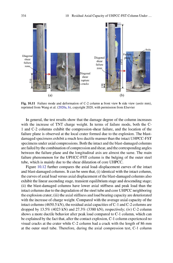
Fig. 10.11 Failure mode and deformation of C-2 column a front view b side view (units mm),
reprinted from Wang et al. (2020a, b), copyright 2020, with permission from Elsevier
In general, the test results show that the damage degree of the column increases
with the increase of TNT charge weight. In terms of failure mode, both the C1 and C-2 columns exhibit the compression-shear failure, and the location of the
failure plane is observed at the local crater formed due to the explosion. The blastdamaged specimens exhibit a much less ductile manner than the intact UHPCC-FST
specimens under axial compressions. Both the intact and the blast-damaged columns
are failed by the combination of compression and shear, and the corresponding angles
between the failure plane and the longitudinal axis are almost the same. The main
failure phenomenon for the UPHCC-FST column is the bulging of the outer steel
tube, which is mainly due to the shear dilatation of core UHPCC.
Figure 10.12 further compares the axial load–displacement curves of the intact
and blast-damaged columns. It can be seen that, (i) identical with the intact column,
the curves of axial load versus axial displacement of the blast-damaged columns also
exhibit the linear ascending stage, transient equilibrium stage and descending stage;
(ii) the blast-damaged columns have lower axial stiffness and peak load than the
intact columns due to the degradation of the steel tube and core UHPCC neighboring
the explosion crater; (iii) the axial stiffness and load bearing capacity are deteriorated
with the increase of charge weight. Compared with the average axial capacity of the
intact columns (4650.5 kN), the residual axial capacities of C-1 and C-2 columns are
dropped by 13.5% (4023 kN) and 27.3% (3380 kN), respectively; (iv) C-2 column
shows a more ductile behavior after peak load compared to C-1 column, which can
be explained by the fact that, after the contact explosion, C-1 column experienced no
visual cracks at the crater while C-2 column had a crack with the length of 86 mm
at the outer steel tube. Therefore, during the axial compression test, C-1 column
10 Residual Axial Capacity of UHPCC-FST Column Under …
150
510
Diagonal
shear
failure
zone
Diagonal
shear
rupture
cracks
510
150
Diagonal
shear
failure
zone
1975
Failure
plane
Axis
(a)
(b)
Fig. 10.11 Failure mode and deformation of C-2 column a front view b side view (units mm),
reprinted from Wang et al. (2020a, b), copyright 2020, with permission from Elsevier
In general, the test results show that the damage degree of the column increases
with the increase of TNT charge weight. In terms of failure mode, both the C1 and C-2 columns exhibit the compression-shear failure, and the location of the
failure plane is observed at the local crater formed due to the explosion. The blastdamaged specimens exhibit a much less ductile manner than the intact UHPCC-FST
specimens under axial compressions. Both the intact and the blast-damaged columns
are failed by the combination of compression and shear, and the corresponding angles
between the failure plane and the longitudinal axis are almost the same. The main
failure phenomenon for the UPHCC-FST column is the bulging of the outer steel
tube, which is mainly due to the shear dilatation of core UHPCC.
Figure 10.12 further compares the axial load–displacement curves of the intact
and blast-damaged columns. It can be seen that, (i) identical with the intact column,
the curves of axial load versus axial displacement of the blast-damaged columns also
exhibit the linear ascending stage, transient equilibrium stage and descending stage;
(ii) the blast-damaged columns have lower axial stiffness and peak load than the
intact columns due to the degradation of the steel tube and core UHPCC neighboring
the explosion crater; (iii) the axial stiffness and load bearing capacity are deteriorated
with the increase of charge weight. Compared with the average axial capacity of the
intact columns (4650.5 kN), the residual axial capacities of C-1 and C-2 columns are
dropped by 13.5% (4023 kN) and 27.3% (3380 kN), respectively; (iv) C-2 column
shows a more ductile behavior after peak load compared to C-1 column, which can
be explained by the fact that, after the contact explosion, C-1 column experienced no
visual cracks at the crater while C-2 column had a crack with the length of 86 mm
at the outer steel tube. Therefore, during the axial compression test, C-1 column