

10.5 Axial Compression Test
333
diagonal shear failure. Due to the local detonation damage of the column, the excessive compressive displacement was likely to cause brittle failure of the specimen,
thus the axial compression test was ended when the axial load dropped to about 60%
of the maximum axial load.
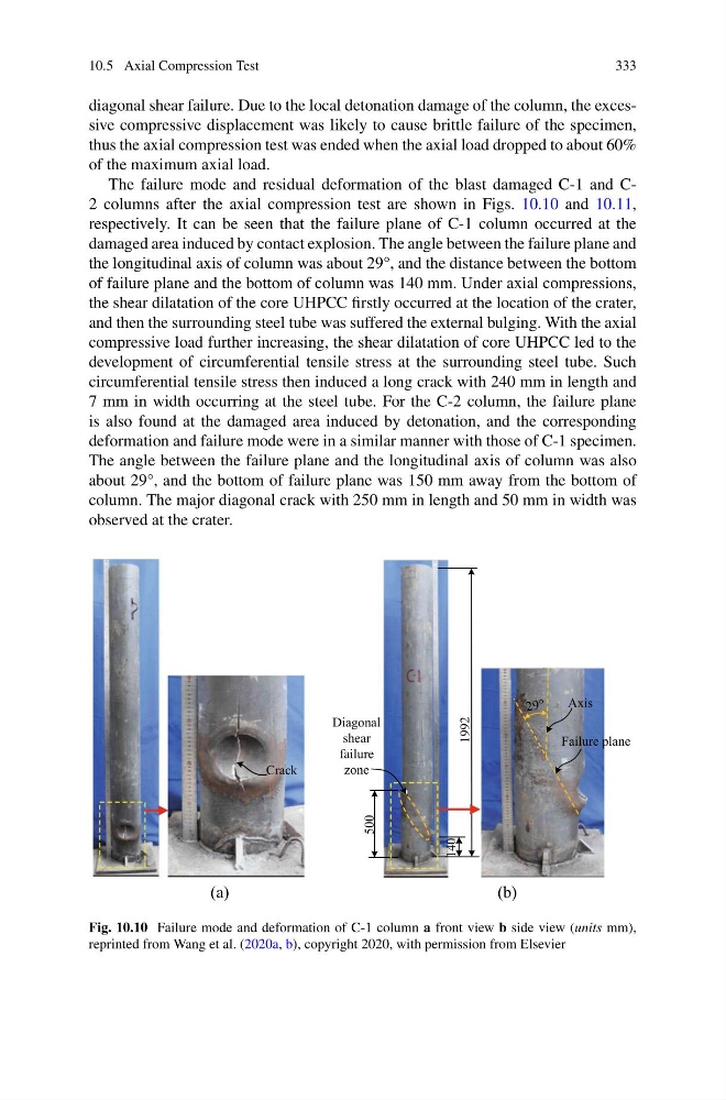
The failure mode and residual deformation of the blast damaged C-1 and C2 columns after the axial compression test are shown in Figs. 10.10 and 10.11,
respectively. It can be seen that the failure plane of C-1 column occurred at the
damaged area induced by contact explosion. The angle between the failure plane and
the longitudinal axis of column was about 29°, and the distance between the bottom
of failure plane and the bottom of column was 140 mm. Under axial compressions,
the shear dilatation of the core UHPCC firstly occurred at the location of the crater,
and then the surrounding steel tube was suffered the external bulging. With the axial
compressive load further increasing, the shear dilatation of core UHPCC led to the
development of circumferential tensile stress at the surrounding steel tube. Such
circumferential tensile stress then induced a long crack with 240 mm in length and
7 mm in width occurring at the steel tube. For the C-2 column, the failure plane
is also found at the damaged area induced by detonation, and the corresponding
deformation and failure mode were in a similar manner with those of C-1 specimen.
The angle between the failure plane and the longitudinal axis of column was also
about 29°, and the bottom of failure plane was 150 mm away from the bottom of
column. The major diagonal crack with 250 mm in length and 50 mm in width was
observed at the crater.
Crack
140
500
Diagonal
shear
failure
zone
1992
Failure plane
Axis
(a)
(b)
Fig. 10.10 Failure mode and deformation of C-1 column a front view b side view (units mm),
reprinted from Wang et al. (2020a, b), copyright 2020, with permission from Elsevier
333
diagonal shear failure. Due to the local detonation damage of the column, the excessive compressive displacement was likely to cause brittle failure of the specimen,
thus the axial compression test was ended when the axial load dropped to about 60%
of the maximum axial load.
The failure mode and residual deformation of the blast damaged C-1 and C2 columns after the axial compression test are shown in Figs. 10.10 and 10.11,
respectively. It can be seen that the failure plane of C-1 column occurred at the
damaged area induced by contact explosion. The angle between the failure plane and
the longitudinal axis of column was about 29°, and the distance between the bottom
of failure plane and the bottom of column was 140 mm. Under axial compressions,
the shear dilatation of the core UHPCC firstly occurred at the location of the crater,
and then the surrounding steel tube was suffered the external bulging. With the axial
compressive load further increasing, the shear dilatation of core UHPCC led to the
development of circumferential tensile stress at the surrounding steel tube. Such
circumferential tensile stress then induced a long crack with 240 mm in length and
7 mm in width occurring at the steel tube. For the C-2 column, the failure plane
is also found at the damaged area induced by detonation, and the corresponding
deformation and failure mode were in a similar manner with those of C-1 specimen.
The angle between the failure plane and the longitudinal axis of column was also
about 29°, and the bottom of failure plane was 150 mm away from the bottom of
column. The major diagonal crack with 250 mm in length and 50 mm in width was
observed at the crater.
Crack
140
500
Diagonal
shear
failure
zone
1992
Failure plane
Axis
(a)
(b)
Fig. 10.10 Failure mode and deformation of C-1 column a front view b side view (units mm),
reprinted from Wang et al. (2020a, b), copyright 2020, with permission from Elsevier