

10.6 Numerical Simulation
337
Steel tube
UHPCC
TNT charge
Air domain
Rigid ground
Steel support
x
y
z
Steel plate
(a)
UHPCC-FST column
Ball joint
Bearing plate
x
y
z
Steel plate
Moving direction
Rigid ground
(b)
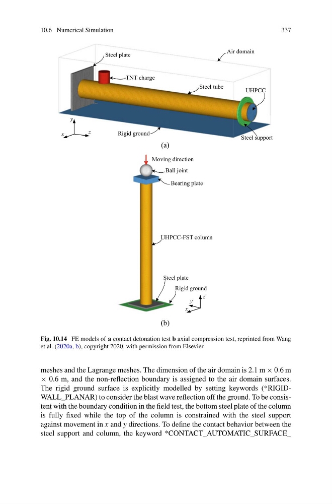
Fig. 10.14 FE models of a contact detonation test b axial compression test, reprinted from Wang
et al. (2020a, b), copyright 2020, with permission from Elsevier
meshes and the Lagrange meshes. The dimension of the air domain is 2.1 m × 0.6 m
× 0.6 m, and the non-reflection boundary is assigned to the air domain surfaces.
The rigid ground surface is explicitly modelled by setting keywords (*RIGIDWALL_PLANAR) to consider the blast wave reflection off the ground. To be consistent with the boundary condition in the field test, the bottom steel plate of the column
is fully fixed while the top of the column is constrained with the steel support
against movement in x and y directions. To define the contact behavior between the
steel support and column, the keyword *CONTACT_AUTOMATIC_SURFACE_
337
Steel tube
UHPCC
TNT charge
Air domain
Rigid ground
Steel support
x
y
z
Steel plate
(a)
UHPCC-FST column
Ball joint
Bearing plate
x
y
z
Steel plate
Moving direction
Rigid ground
(b)
Fig. 10.14 FE models of a contact detonation test b axial compression test, reprinted from Wang
et al. (2020a, b), copyright 2020, with permission from Elsevier
meshes and the Lagrange meshes. The dimension of the air domain is 2.1 m × 0.6 m
× 0.6 m, and the non-reflection boundary is assigned to the air domain surfaces.
The rigid ground surface is explicitly modelled by setting keywords (*RIGIDWALL_PLANAR) to consider the blast wave reflection off the ground. To be consistent with the boundary condition in the field test, the bottom steel plate of the column
is fully fixed while the top of the column is constrained with the steel support
against movement in x and y directions. To define the contact behavior between the
steel support and column, the keyword *CONTACT_AUTOMATIC_SURFACE_