

10.4 Field Contact Explosion Test
329
(a)
(b)
(c)
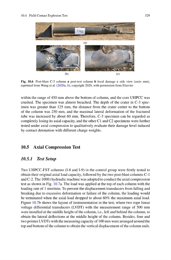
Fig. 10.6 Post-blast C-3 column a post-test column b local damage c side view (units mm),
reprinted from Wang et al. (2020a, b), copyright 2020, with permission from Elsevier
within the range of 450 mm above the bottom of column, and the core UHPCC was
crushed. The specimen was almost breached. The depth of the crater in C-3 specimen was greater than 125 mm, the distance from the crater center to the bottom
of the column was 250 mm, and the maximal lateral deformation of the fractured
tube was increased by about 60 mm. Therefore, C-3 specimen can be regarded as
completely losing its axial capacity, and the other C1 and C2 specimens were further
tested under axial compression to qualitatively evaluate their damage level induced
by contact detonation with different charge weights.
10.5 Axial Compression Test
10.5.1 Test Setup
Two UHPCC-FST columns (I-8 and I-9) in the control group were firstly tested to
obtain their original axial load capacity, followed by the two post-blast columns C-1
and C-2. The 1000 t hydraulic machine was adopted to conduct the axial compression
test as shown in Fig. 10.7a. The load was applied at the top of each column with the
loading rate of 1 mm/min. To prevent the displacement transducers from falling and
breaking due to excessive deformation or failure of the column, the loading would
be terminated when the axial load dropped to about 60% the maximum axial load.
Figure 10.7b shows the layout of instrumentation in the test, where two rope linear
voltage differential transducers (LVDT) with the measurement range of 500 mm
were installed at the middle height of the column, i.e., left and behind the column, to
obtain the lateral deflections at the middle height of the column. Besides, four and
two pointer LVDTs with the measuring capacity of 100 mm were arranged around the
top and bottom of the column to obtain the vertical displacement of the column ends.
329
(a)
(b)
(c)
Fig. 10.6 Post-blast C-3 column a post-test column b local damage c side view (units mm),
reprinted from Wang et al. (2020a, b), copyright 2020, with permission from Elsevier
within the range of 450 mm above the bottom of column, and the core UHPCC was
crushed. The specimen was almost breached. The depth of the crater in C-3 specimen was greater than 125 mm, the distance from the crater center to the bottom
of the column was 250 mm, and the maximal lateral deformation of the fractured
tube was increased by about 60 mm. Therefore, C-3 specimen can be regarded as
completely losing its axial capacity, and the other C1 and C2 specimens were further
tested under axial compression to qualitatively evaluate their damage level induced
by contact detonation with different charge weights.
10.5 Axial Compression Test
10.5.1 Test Setup
Two UHPCC-FST columns (I-8 and I-9) in the control group were firstly tested to
obtain their original axial load capacity, followed by the two post-blast columns C-1
and C-2. The 1000 t hydraulic machine was adopted to conduct the axial compression
test as shown in Fig. 10.7a. The load was applied at the top of each column with the
loading rate of 1 mm/min. To prevent the displacement transducers from falling and
breaking due to excessive deformation or failure of the column, the loading would
be terminated when the axial load dropped to about 60% the maximum axial load.
Figure 10.7b shows the layout of instrumentation in the test, where two rope linear
voltage differential transducers (LVDT) with the measurement range of 500 mm
were installed at the middle height of the column, i.e., left and behind the column, to
obtain the lateral deflections at the middle height of the column. Besides, four and
two pointer LVDTs with the measuring capacity of 100 mm were arranged around the
top and bottom of the column to obtain the vertical displacement of the column ends.